
Installation Manual


5
CODES AND REGULATIONS
The GPH M-Series heat pumps are designed for OUTDOOR USE ONLY. *PH M-Series is available in cooling capacities of 2, 2.5, 3, 3 1/2
and 4 nominal tons of cooling. Optional field installed heat kits are available in 5,8,10,15 and 20 kW. The units can be easily installed
in manufactured or modular homes with existing high-static duct work. The units can also be easily converted to accommodate a
plenum for normal or low-static applications. The GPH M-Series are self contained packaged units so the only connections needed for
installation are the supply and return ducts, the line and low voltage wiring and drain connection. Rated performance is achieved after
72 hours of operation. Rated performance is delivered at the specified airflow. See outdoor unit specification sheet for split system
models or product specification sheet for packaged and light commercial models. Specification sheets can be found at
www.goodmanmfg.com for Goodman
®
brand products. Within either website, please select the residential or commercial products
menu and then select the submenu for the type of product to be installed, such as air conditioners or heat pumps, to access a list of
product pages that each contain links to that model’s specification sheet. The units are ETL listed and AHRI certified.
The information on the rating plate is in compliance with the FTC & DOE rating for single phase units.
EPA REGULATIONS
IMPORTANT: THE UNITED STATES ENVIRONMENTAL PROTECTION AGENCY (EPA) HAS ISSUED VARIOUS REGULATIONS REGARDING THE INTRODUCTION
AND
DISPOSAL OF REFRIGERANTS IN THIS UNIT. FAILURE TO FOLLOW THESE REGULATIONS MAY HARM THE ENVIRONMENT AND CAN LEAD TO THE
IMPOSITION
OF SUBSTANTIAL FINES. BECAUSE REGULATIONS MAY VARY DUE TO PASSAGE OF NEW LAWS, WE SUGGEST A CERTIFIED TECHNICIAN
PERFORM
ANY WORK DONE ON THIS UNIT. SHOULD YOU HAVE ANY QUESTIONS PLEASE CONTACT THE LOCAL OFFICE OF THE EPA.
NATIONAL C ODES
This product is designed and manufactured to permit installation in accordance with National Codes. It is the installer’s responsibility
to install the product in accordance with National Codes and/or prevailing local codes and regulations.
MAJOR COMPONENTS
The unit includes a hermetically sealed refrigerating system (consisting of a compressor, condenser coil, evaporator coil with flowrator),
an indoor blower, a condenser fan and all necessary internal electrical wiring. The heat pump also includes a reversing valve, solenoid,
defrost thermostat and control and loss of charge protection. The system is factory-evacuated, charged and performance tested.
Refrigerant amount and type are indicated on rating plate.
PRE-INSTALLATION CHECKS
Before attempting any installation, the following points should be considered:
• Structural strength of supporting members
• Clearances and provision for servicing
• Power supply and wiring
• Air duct connections
• Drain facilities and connections
• Location may be on any four sides of a home, manufactured or modular, to minimize noise
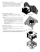
CLEARANCES AND A CCESSIBILITY
The unit is designed to be located outside the building with unobstructed condenser air inlet and discharge. Additionally, the unit
must be situated to permit access for service and installation. Condenser air enters from three sides. Air discharges upward from
the top of the unit. Refrigerant gauge connections are made on the right side of the unit as you face the compressor compartment.
Electrical connections can be made either on the right, bottom or duct panel side of the unit. The best and most common
application is for the unit to be located 10” from wall (4” minimum) with the connection side facing the wall. This “close to the wall”
application minimizes exposed wiring.
Close to the wall application assures free, unobstructed air to the other two sides. In more confined application spaces, such as
corners provide a minimum 12” clearance on all air inlet sides. Allow 36” minimum for service access to the compressor
compartment and controls. The top of the unit should be completely unobstructed. If units are to be located under an overhang,
there should be a minimum of 48” clearance and provisions made to deflect the warm discharge air out from the overhang.
UNIT LOCATION
Consider the affect of outdoor fan noise on conditioned space and any adjacent occupied space. It is recommended that the unit
be placed so that condenser air discharge does not blow toward windows less than 25 feet away. Consideration should also be
given to shade and unit appearance.
Heat pumps require special location consideration in areas of heavy snow accumulation and/or areas with prolonged continuous
subfreezing temperatures. Heat pump unit bases have holes under the outdoor coil to permit drainage of defrost water accumulation.
The unit must be situated to permit free unobstructed drainage of the defrost water and ice. A minimum 2" clearance under the
outdoor coil is required in the milder climates.