
Installation Manual


9
LOW V OLTAGE W IRING
• Heat Pumps. Connect 24V wires from the thermostat to the
corresponding wires in the control box using No. 18 AWG as follows:
NOTE: All GPH16 units have two-stage cooling and require two-stage
heat/cool with optional third stage electric heat thermostat.
Terminal Thermostat
Red R (24V)
Green G (fan)
Orange O (rev. valve)
White W1 (heat, 2nd)
Brown W2 (heat, 3rd)
Purple Y1 (low cool)
Yellow Y2 (high cool)
Blue C (24V Common)
Thermostats must be set to energize "G" during cooling.
This is default on most all thermostats.
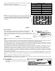
GPH1624 - 48
BRANCH CIRCUIT AMPACITY
15 20 25 30 35 40 45 50
SUPPLY WIRE LENGTH -
FEET
200 64443322
150 86644433
100 108866644
50 141210108866
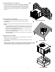
INTERNAL W IRING
A diagram detailing the internal wiring of this unit is located on the
electrical box cover. If any of the original wire supplied with the
appliance must be replaced, the wire gauge and insulation must
be the same as the original wiring.
Transformer is wired for 230 volts on the 208/230 models. See
wiring diagram for 208 volt wiring.
1. For branch circuit wiring (main power supply to unit disconnect),
the minimum wire size for the length of run can be determined
using the circuit ampacity found on the unit rating plate and the
table below. From the unit disconnect to the unit, the smallest wire size allowable may be used for the ampacity, as the
disconnect must be in sight of the unit.
2. Wire size based on 60°C rated wire insulation and 30°C Ambient Temperature (86°F).
3. For more than three conductors in a raceway or cable, see the N.E.C. for derating the ampacity of each conductor.
STARTUP, ADJUSTMENTS, AND CHECKS
C
OOLING S TART-UP P ROCEDURES
With power turned off at all disconnects:
1. Turn thermostat system switch to “COOL” and fan switch to
“AUTO”. Next, turn the temperature setting as high as it will
go.
2. Inspect all registers and set them to the normal open
position.
3. Turn on the electrical supply at the disconnect.
4. Turn the fan switch to the “ON” position. The blower should begin ramping up immediately.
5. Turn the fan switch to “AUTO” position. The blower should begin ramping down after an approximate 60-second delay.
6. Slowly lower the cooling temperature until the unit starts. The compressor, blower and fan should now be operating. Allow the
unit to run 10 minutes, make sure cool air is being supplied by the unit.
7. Turn the temperature setting to the highest position, stopping the unit. The indoor blower will continue to run for approximately
60-seconds.
8. Turn the thermostat system switch to “OFF” and disconnect all power when servicing the unit.
HEAT PUMP START-UP PROCEDURE
1. Check the cooling mode for the heat pump in the same manner as above. The reversing valve is energized when the thermostat
is placed in the cooling position. A clicking sound should be noticeable from the reversing valve. By lowering the temperature
setting to call for cooling, the contractor is energized. The compressor, blower and fan should then be running. After the cooling
mode is checked out, turn the thermostat system switch to “OFF”.
2. Turn the thermostat system switch to “HEAT” and fan switch to “AUTO”.
3. Slowly raise the heating temperature setting. When the heating first stage makes contact, stop raising the temperature setting..
The compressor, blower and fan should now be running with the reversing valve in the de-energized (heating) position. After
giving the unit time to settle out, make sure the unit is supplying heated air.