
Installation Manual


10
House depressurization can cause back drafting or improper
-
ing occupants to gas combustion products that could include
carbon monoxide.
If this furnace is to be installed in the same space with other
gas appliances, such as a water heater, ensure there is an ad-
equate supply of combustion and ventilation air for the other
-
lation Codes or applicable provisions of the local building
codes for determining the combustion air requirements for
the appliances.
Most homes will require outside air be supplied to the fur-
nace area by means of ventilation grilles or ducts connecting
directly to the outdoors or spaces open to the outdoors such
as attics or crawl spaces.
This furnace may be installed in an upright position or hor-
upright upow furnaces, return
horizontal upow furnaces, return air
up-
right or horizontal counterow furnaces, return ductwork
to the back of the furnace. Contact your distributor for
proper airflow requirements and number of required
ductwork connections. Refer to “Recommended Installa-
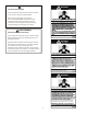
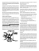
2" 2" 3/8"
ANGLE
IRON
(3
PLACES
)
X X
must be given to the following:
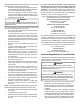
If suspending the furnace from rafters or joists, use 3/8” thread-
ed rod and 2”x2”x1/8” angle iron as shown in the following
diagram. The length of rod will depend on the application
and the clearances necessary.
If the furnace is installed in a crawl space it must be sus-
Never install the furnace on the ground or allow it to be
exposed to water.
the front cover pressure switch tube must be re-located to
the lower port of the collector box cover.
1. Remove tube from front cover pressure switch and
collector box cover.
2. Remove rubber plug from bottom collector box port
and install on top collector box port.
3. Locate 24” x 1/4” tube in bag assembly.
4. Install one end on front cover pressure switch.
5. Route tube to lower port on collector box cover and
In horizontal applications the condensate drain trap is secured
to the furnace side panel, suspending it below the furnace.
A minimum clearance of 5.5” below the furnace must be
provided for the drain trap. Additionally, the appropriate
downward piping slope must be maintained from the drain
trap to the drain location. Refer to Condensate Drain Trap
and Lines for further details. If the drain trap and drain line
will be exposed to temperatures near or below freezing,
adequate measures must be taken to prevent condensate
from freezing.
Leveling ensures proper condensate drainage from the heat
be level lengthwise from end to end. The furnace should
have a slight tilt from back to front with the access doors
downhill fromthe back panel approximately 1/2 to 3/4
inches. The slight tilt allows the heat exchanger condensate,
-
perator coil frontcover.
-
air piping to be run vertically through the side of the fur-
nace. Refer to the “Recommended Installation Positions”
ent/Flue