
Instructions / Assembly


10
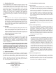
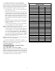
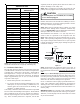
LIQUID PRESSURE
PSIG R-22 R-410A
200 101 70
210 105 73
220 108 76
225 110 78
235 113 80
245 116 83
255 119 85
265 121 88
275 124 90
285 127 92
295 130 95
305 133 97
325 137 101
355 144 108
375 148 112
405 155 118
415 157 119
425 n/a 121
435 n/a 123
445 n/a 125
475 n/a 130
500 n/a 134
525 n/a 138
550 n/a 142
575 n/a 145
600 n/a 149
625 n/a 152
SATURATED LIQUID PRESSURE
TEMPERATURE CHART
SATURATED LIQUID
TEMPERATURE ºF
NOTE: Units matched with indoor coils equipped with non-
adjustable TXV should be charged by subcooling only.
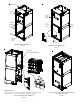
8 Condensate Drain Lines
The coil drain pan has a primary and a secondary drain with
3/4" NPT female connections. The connectors required are
3/4" NPT male, either PVC or metal pipe, and should be
hand tightened to a torque of no more than 37 in-lbs. to
prevent damage to the drain pan connection. An insertion
depth of approximately 3/8” to 1/2” (3-5 turns) should be
expected at this torque.
1. Ensure drain pan hole is not obstructed.
2. To prevent potential sweating and dripping on to fin-
ished space, it may be necessary to insulate the con-
densate drain line located inside the building. Use
Armaflex
®
or similar material.
A secondary condensate drain connection has been provided
for areas where the building codes require it. Pitch all drain
lines a minimum of 1/4" per foot to provide free drainage.
Provide required support to the drain line to prevent bow-
ing. If the secondary drain line is required, run the line
separately from the primary drain and end it where con-
densate discharge can be easily seen.
NOTE: Water coming from secondary line means the coil
primary drain is plugged and needs immediate attention.
CAUTION
If secondary drain is not installed, the secondary
access must be plugged.
Insulate drain lines located inside the building or above a
finished living space to prevent sweating. Install a conden-
sate trap to ensure proper drainage.
NOTE: When units are installed above ceilings, or in other
locations where damage from condensate overflow may
occur, it is MANDATORY to install a field fabricated auxiliary
drain pan under the coil cabinet enclosure.
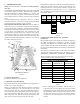
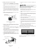
The installation must include a “P” style trap that is lo-
cated as close as is practical to the evaporator coil. See
Figure 12 for details of a typical condensate line “P” trap.
NOTE: Units operating in high static pressure applications
may require a deeper field constructed “P” style trap than
is shown in Figure 12 to allow proper drainage and prevent
condensate overflow.
Air Handler
3" MIN.
POSITIVE LIQUID
SEAL REQUIRED
AT TRAP
Drain
Connection
2" MIN.
Figure 12
NOTE: Trapped lines are required by many local codes. In
the absence of any prevailing local codes, please refer to
the requirements listed in the Uniform Mechanical Building
Code.
A drain trap in a draw-through application prevents air from
being drawn back through the drain line during fan opera-
tion thus preventing condensate from draining, and if con-
nected to a sewer line to prevent sewer gases from being
drawn into the airstream during blower operation.
Use of a condensate removal pump is permitted when nec-
essary. This condensate pump should have provisions for
shutting off the control voltage should a blocked drain oc-
cur. A trap must be installed between the unit and the con-
densate pump.
IMPORTANT NOTE: The evaporator coil is fabricated with
oils that may dissolve styrofoam and certain types of plastics.
Therefore, a removal pump or float switch must not contain
any of these materials.