
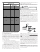
Instructions / Assembly

3
2 Shipping Inspection
Always transport the unit upright; laying the unit on its side
or top during transit may cause equipment damage. The
installer should inspect the product upon receipt for ship-
ping damage and subsequent investigation is the responsi-
bility of the carrier. The installer must verify the model
number, specifications, electrical characteristics, and ac-
cessories are correct prior to installation. The distributor
or manufacturer will not accept claims from dealers for
transportation damage or installation of incorrectly shipped
units.
2.1 Parts
Also inspect the unit to verify all required components
are present and intact. Report any missing components
immediately to the manufacturer or to the distributor.
Use only factory authorized replacement parts (see Sec-
tion 5). Make sure to include the full product model
number and serial number when reporting and/or ob-
taining service parts.
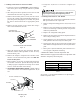
2.2 Handling
Use caution when transporting/carrying the unit. Do not
move unit using shipping straps. Do not carry unit with
hooks or sharp objects. The preferred method of car-
rying the unit after arrival at the job site is to carry via
a two-wheel hand truck from the back or sides or via
hand by carrying at the cabinet corners.
3 Codes & Regulations
This product is designed and manufactured to comply with
applicable national codes. Installation in accordance with
such codes and/or prevailing local codes/regulations is the
responsibility of the installer. The manufacturer assumes
no responsibility for equipment installed in violation of any
codes or regulations.
The United States Environmental Protection Agency (EPA)
has issued various regulations regarding the introduction
and disposal of refrigerants. Failure to follow these regu-
lations may harm the environment and can lead to the
imposition of substantial fines. Should you have any ques-
tions please contact the local office of the EPA and/or re-
fer to EPA’s website www.epa.gov.
4 Replacement Parts
When reporting shortages or damages, or ordering repair
parts, give the complete product model and serial numbers
as stamped on the product. Replacement parts for this
product are available through your contractor or local dis-
tributor. For the location of your nearest distributor con-
sult the white business pages, the yellow page section of
the local telephone book or contact:
HOMEOWNER SUPPORT
GOODMAN MANUFACTURING COMPANY, L.P.
19001 KERMIER ROAD
WALLER, TEXAS 77484
(877) 254-4729
5 Pre-Installation Considerations
5.1 Preparation
Keep this document with the unit. Carefully read all
instructions for the installation prior to installing prod-
uct. Make sure each step or procedure is understood
and any special considerations are taken into account
before starting installation. Assemble all tools, hard-
ware and supplies needed to complete the installation.
Some items may need to be purchased locally. Make
sure everything needed to install the product is on hand
before starting.
5.2 System Matches
The entire system (combination of indoor and outdoor
sections) must be manufacturer approved and Air-Con-
ditioning, Heating, and Refrigeration Institute (AHRI)
listed. NOTE: Installation of unmatched systems is not
permitted.
5.3 Interconnecting Tubing
Give special consideration to minimize the length of
refrigerant tubing when installing air handlers. Refer
to Remote Cooling/Heat Pump Service Manual
RS6200006, and TP-107 Long Line Set Application R-
410A for tubing guidelines. If possible, allow adequate
length of tubing such that the coil may be removed (for
inspection or cleaning services) from the cabinet with-
out disconnecting the tubing.
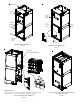
5.4 Clearances
The unit clearance from a combustible surface may be
0". However, service clearance must take precedence.
A minimum of 24" in front of the unit for service clear-
ance is required. Additional clearance on one side or
top will be required for electrical wiring connections.
Consult all appropriate regulatory codes prior to de-
termining final clearances. When installing this unit in
an area that may become wet (such as crawl spaces),
elevate the unit with a sturdy, non-porous material. In
installations that may lead to physical damage (i.e. a
garage) it is advised to install a protective barrier to
prevent such damage. Always install units such that a
positive slope in condensate line (1/4" per foot) is al-
lowed.
5.5 Horizontal Applications
If installed above a finished living space, a secondary
drain pan (as required by many building codes), must
be installed under the entire unit and its condensate
drain line must be routed to a location such that the
user will see the condensate discharge.