
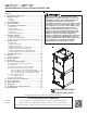
Instructions / Assembly


4
6 Installation Location
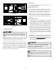
NOTE: These air handlers are designed for indoor installa-
tion only.
The ARUF**14** and ASPT**14** product lines may be installed
in one of the upflow, downflow, horizontal left or horizon-
tal right orientations as shown in Figures 2, 3, 4 and 5. The
unit may be installed in upflow or horizontal left orienta-
tion as shipped (refer to specific sections for more informa-
tion).
No field modifications are mandatory. However, to obtain
maximum efficiency, the horizontal drip shield, side drain
pan and drain pan extension can be removed.
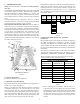
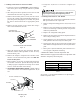
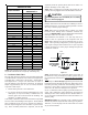
Side Drain Pan and Extension Removal: Refer to Figure 1,
remove the two (2) screws that secure the drip shield sup-
port brackets to the condensate collectors (front and back).
Unsnap the side drain pan from the bottom drain pan using
a screw driver or any small lever. The side drain pan, drip
shield brackets and the drain pan extension may now be
removed. From Figure 1, drain port labeled (A) is the pri-
mary drain for this application and condensate drain line
must be attached to this drain port. Drain port (a) is for the
secondary drain line (if used).
D
rip Pan
E
xtension
Side
Drain
Pan
Screw
B
b
A
Main Drain Pan
Drip Shield Bracket
Drip Shield
Pna
SIDE DRAIN PAN REMOVAL
Figure 1
6.1 Upflow Installation
No field modifications are mandatory.
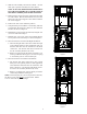
6.2 Horizontal Left Installation
No field modifications are permissible for this application.
Install unit as shown in Figure 4.
Remove red plugs from side drain pan before connecting
condensate drain pipes. Use removed plug to close drain
ports on vertical drain pan. The bottom right drain connec-
tion in side drain pan is the primary drain for this applica-
tion and condensate drain line must be attached to this
drain connection. The bottom left drain connection in side
drain pan is for the secondary drain line (if used).
In applications where the air handler is installed in the hori-
zontal left position, and the return air environment see
humidity levels above 65% relative humidity coupled with
total external static levels above 0.5” e.s.p., a condensate
kit is available for field application. Kit nomenclature can
be found in Table 1.
CMK0008
Condensate
Kit
CMK0009
Condensate
Kit
CMK0010
Condensate
Kit
CMK0011
Condensate
Kit
CMK0012
Condensate
Kit
CMK0013
Condensate
Kit
CMK0014
Condensate
Kit
ARUF25B14 ARUF31B14 ARUF37C14 ARUF47D14 ARUF61D14 ASPT33C14 ASPT49C14
ARUF29B14 ASPT29B14 ARUF37D14 ASPT49D14 ASPT39C14
ASPT25B14 ASPT37B14 ARUF43C14 ASPT61D14
ARUF43D14
ARUF49C14
ARUF49D14
ASPT37C14
ASPT47C14
ASPT47D14
ASPT59C14
CONDENSATE KIT
Table 1
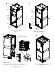
6.3 Horizontal Right Installation / Downflow
Installation
When installing unit in the downflow position the appropri-
ate (DFK) downflow kit is required to prevent “coil pan
sweating”. The DFK kit is not supplied with the air handler
and is available through your local distributor. See Table 2
for the correct DFK and follow the instructions provided for
installation.
Side drain pan extension must be removed in the downflow
and horizontal right applications for all models except:
ARUF47D14**, ARUF61D14**, ASPT61D14**, ASPT49D14**.
Refer to Figure 6 and 7 for the location of the compo-
nents referenced in the following steps.
DFK-B
DOWNFLOW KIT
DFK-C
DOWNFLOW KIT
DFK-D
DOWNFLOW KIT
ARUF25B14** ARUF37C14** ARUF37D14**
ARUF29B14** ARUF43C14** ARUF43D14**
ARUF31B14** ARUF49C14** ARUF47D14**
ASPT25B14** ASPT33C14** ARUF49D14**
ASPT29B14** ASPT37C14** ARUF61D14**
ASPT35B14** ASPT39C14** ASPT61D14**
ASPT37B14** ASPT47C14** ASPT47D14**
ASPT49C14** ASPT49D14**
ASPT59C14**
MODEL LIST FOR DOWNFLOW KIT
DOWNFLOW KIT
Table 2
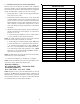
1. Before inverting the air handler, remove blower ac-
cess panel and coil access panel. The coil access panel
and tubing panel may remain screwed together during
this procedure. Remove and retain the seven (7) screws
securing the coil access panel to the cabinet and the
six (6) screws securing the blower access panel to the
cabinet.