
Instructions / Assembly


5
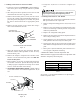
2. Slide the coil assembly out from the cabinet. Use the
drain pan to pull the assembly from the cabinet.
NOTE: DO NOT USE MANIFOLDS OR FLOWRATOR TO
PULL THE COIL ASSEMBLY OUT. FAILURE TO DO SO
MAY RESULT IN BRAZE JOINT DAMAGE AND LEAKS.
3. Removal of the center support is required on units with
21" wide cabinet. Remove and retain the two (2) screws
that secure the center support to the cabinet. Remove
the center support.
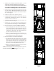
4. Position the unit in the downflow position.
5. Using the drain pan to hold the coil assembly, slide the
coil assembly back into the cabinet on the downflow
brackets as shown in Figure 8.
6. Reinstall the center support (if removed) using the two
(2) screws removed in Step 5.
7. Reinstall the coil access panels and reinstall blower
access panel removed in Step 1 as shown in Figure 9.
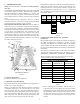
8. Drain Connections for Horizontal Right Installation
a. The bottom right drain connection in side drain pan
is the primary drain for this application and con-
densate drain line must be attached to this drain
connection. The bottom left drain connection is
for the secondary drain line (if used).
b. Remove red plugs from side drain pan before con-
necting condensate drain pipes. Use removed plug
to close drain ports on vertical drain pan.
9. Drain Connections for Downflow Installation
a. The bottom left drain connection in the vertical
drain pan is the primary drain for this application
and condensate drain line must be attached to this
drain connection. The bottom right drain connec-
tion is for the secondary drain line (if used).
b. Remove red plugs from vertical drain pan before
connecting condensate drain pipes.
NOTE: If removing only the coil access panel from the unit,
the filter access panel must be removed first. Failure
to do so will result in panel damage.
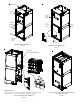
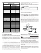
UPFLOW
Figure 2
DOWNFLOW
Figure 3