
Instructions / Assembly


6
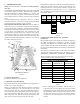
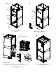
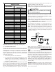
HORIZONTAL LEFT
Figure 4
HORIZONTAL RIGHT
Figure 5
7 Refrigerant Lines
This product is factory-shipped with R410A and dry
nitrogen mixture gas under pressure. Use appropriate
service tools and follow these instructions to prevent
injury.
NOTE: Refrigerant tubing must be routed to allow adequate
access for servicing and maintenance of the unit.
Do not install the air handler in a location that violates the
instructions provided with the condenser. If the unit is
located in an unconditioned area with high ambient
temperature and/or high humidity, the air handler may be
subject to nuisance sweating of the air handler cabinet.
On these installations, a wrap of 2" fiberglass insulation
with a vapor barrier is recommended.
7.1 Tubing Size
For the correct tubing size, follow the specification for
the condenser/heat pump.
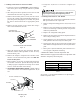
7.2 Tubing Preparation
All cut ends are to be round, burr free, and clean. Fail-
ure to follow this practice increases the chances for
refrigerant leaks. The suction line is spun closed and
requires tubing cutters to remove the closed end.
NOTE: To prevent possible damage to the tubing joints,
do not handle coil assembly with manifold or flowrator
tubes. Always use clean gloves when handling coil as-
semblies.
7.3 Special Instructions
Units without a factory installed TXV come equipped
with a flowrator piston for refrigerant expansion. For
most installations with matching applications, no
change to the flowrator piston is required. However,
in mix-matched applications, a flowrator piston
change may be required. See the piston kit chart (pro-
vided in the literature packet) or consult your local
distributor for details regarding mix-matched
flowrator piston sizing. If the mix-match application
requires a different flowrator piston size, change the
flowrator piston in the flowrator body on the indoor
coil before installing the coil and use the procedure
in section 7.4.
NOTE: The use of a heat shield is strongly recommended
when brazing to avoid burning the serial plate or the
finish of the unit. Heat trap or wet rags must be used
to protect heat sensitive components such as service
valves and TXV valves sensing bulb.
A quenching cloth is strongly recommended to prevent
scorching or marring of the equipment finish when
brazing close to the painted surfaces. Use brazing
alloy of 5% minimum silver content.
Applying too much heat to any tube can melt the tube. Torch
heat required to braze tubes of various sizes must be
proportional to the size of the tube. Service personnel must
use the appropriate heat level for the size of the tube being
brazed.
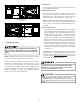
CAUTION