
Instructions / Assembly


8
7.4 Tubing Connections for Flowrator Model
1. Loosen the 13/16 nut 1 TURN ONLY to allow high pres-
sure tracer gas to escape. No gas indicates a possible
leak.
2. After the gas has been expelled, remove the nut and
discard the black or brass cap plastic seal.
3. Remove the flowrator piston to verify it is the correct
size for the outdoor unit being installed and then re-
place the piston (changing size, if needed). See piston
kit chart in the literature kit for appropriate piston
size.
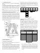
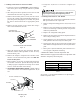
4. Remove the spin closure on the suction line using a
tube cutter and deburr the tube.
RUBBER
GROMMET
SUCTION LINE
WITH SPIN CLOSURE
SUCTION SPUN END AND GROMMET
Figure 10
5. Insert the suction line into the connection, slide the
insulation and the rubber grommet at least 18" away
from the braze joint.
6. Remove the tailpiece clamped to the exterior of the
cabinet or in the literature kit packet and slide the
13/16 nut into place.
7. Braze tailpiece to the line set liquid tube and braze
suction line connection. Quench all brazed joints with
a damp rag upon completion of brazing. Do not allow
water to enter the inside of the tubing.
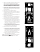
8. AFTER THE TAILPIECE HAS COOLED, confirm position
of the white Teflon
®
seal and hand tighten the 13/16
nut.
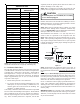
WHITE
TEFLON SEAL
PISTON
TAILPIECE
13/16” NUT
PLASTIC or BRASS CAP
TAILPIECE JOINT
Figure 11
9. Torque the 13/16 nut to 7-25 ft-lbs. or tighten 1/6
turn.
Excessive torque can cause orifices to stick. Use the
proper torque settings when tightening orifices.
7.5 Tubing Connections for TXV Models
TXV models come with factory installed TXV with the
bulb pre-installed on the vapor tube.
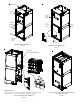
1. Remove refrigerant tubing panel or coil (lower) access
panel.
2. Remove access valve fitting cap and depress the valve
stem in access fitting to release pressure. No pressure
indicates possible leak.
3. Replace the refrigerant tubing panel.
4. Remove the spin closure on both the liquid and suction
tubes using a tubing cutter.
5. Insert liquid line set into liquid tube expansion and
slide grommet about 18" away from braze joint.
6. Insert suction line set into suction tube expansion and
slide insulation and grommet about 18" away from braze
joint.
7. Braze joints. Quench all brazed joints with water or a
wet rag upon completion of brazing.
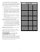
7.6 ASPT**14** Models with Non-Adjustable TXV
ASPT air handlers equipped with Parker non-adjustable TXV
should be charged by subcooling only.
ASPT25B14** ASPT47D14**
ASPT29B14** ASPT47C14**
ASPT37B14** ASPT49D14**
ASPT37C14** ASPT59C14**
Models
Table 3
See section 7.7 for detailed information on adjusting the
thermal expansion valve.