
Instructions / Assembly


9
7.7 Thermal Expansion Valve System Adjustment
Run the system at Cooling for 10 minutes until refrigerant
pressures stabilize. Use the following guidelines and meth-
ods to check unit operation and ensure that the refrigerant
charge is within limits. Charge the unit on low stage.
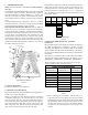
1. Purge gauge lines. Connect service gauge manifold to
base-valve service ports.
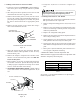
2. Temporarily install a thermometer on the liquid line
at the liquid line service valve and 4-6" from the com-
pressor on the suction line. Ensure the thermometer
makes adequate contact and is insulated for best pos-
sible readings. Use liquid line temperature to deter-
mine subcooling and vapor temperature to determine
superheat.
3. Check subcooling and superheat. Systems with TXV ap-
plication should have a subcooling of 7 to 9ºF and su-
perheat of 7 to 9 ºF.
a. If subcooling and superheat are low, adjust TXV to
7 to 9 ºF superheat, then check subcooling.
NOTE: To adjust superheat, turn the valve stem clockwise
to increase and counter clockwise to decrease.
b. If subcooling is low and superheat is high, add charge
to raise subcooling to 7 to 9ºF then check superheat.
c. If subcooling and superheat are high, adjust TXV
valve to 7 to 9 ºF superheat, then check subcooling.
d. If subcooling is high and superheat is low, adjust
TXV valve to 7 to 9 ºF superheat and remove charge to
lower the subcooling to 7 to 9ºF.
NOTE: Do NOT adjust the charge based on suction pressure
unless there is a gross undercharge.
4. Disconnect manifold set, installation is complete.
NOTE: Check the Schrader ports for leaks and tighten valve
cores if necessary. Install caps finger-tight.
SUBCOOL FORMULA =
SAT. LIQUID LINE TEMP. - LIQUID LINE TEMP.
SUPERHEAT FORMULA =
SUCT. LINE TEMP. - SAT. SUCT. TEMP.
NOTE: Expansion valve system in ASPT models are already
tuned for 16 SEER single stage Heat Pump, adjustment of
Expansion valve system is required in case subcool, superheat
does not match to Section 7.6.3 above or when these models
are installed with any other outdoor models.
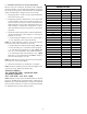
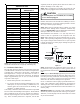
SUCTION PRESSURE
PSIG R-22 R-410A
50 26 1
52 28 3
54 29 4
56 31 6
58 32 7
60 34 8
62 35 10
64 37 11
66 38 13
68 40 14
70 41 15
72 42 16
74 44 17
76 45 19
78 46 20
80 48 21
85 50 24
90 53 26
95 56 29
100 59 31
110 64 36
120 69 41
130 73 45
140 78 49
150 83 53
160 86 56
170 90 60
SATURATED SUCTION PRESSURE
TEMPERATURE CHART
SATURATED SUCTION