
Service Manual


SERVICING
114
Charge the system with the exact amount of refrigerant. Refer to
the specification section or check the unit nameplates for the
correct refrigerant charge. An inaccurately charged system will
cause future problems.
NOTE: R410A should be drawn out of the storage container or
drum in liquid form due to its fractionation properties, but
should be “Flashed” to its gas state before entering the system.
There is commercially available restriction devices that fit into
the system charging hose set to accomplish this.
DO NOT charge
liquid R410A into the compressor.
NOTE: Power must be supplied to the 18 SEER outdoor units
containing ECM motors before the power is applied to the indoor
unit. Sending a low voltage signal without high voltage power
present at the outdoor unit can cause malfunction of the control
module on the ECM motor.
Adequate refrigerant charge for the matching evaporator coil or
air handler and 15 feet of line set is supplied with the condensing
unit. If using evaporator coils or air handlers other than HSVTC
coil it may be necessary to add or remove refrigerant to attain
proper charge. If line set exceeds 15 feet in length, refrigerant
should be added at .6 ounces per foot of liquid line.
NOTE: The outdoor temperature should be 60°F or higher when
charging the unit.Charge should always be checked using
subcooling when using TXV equipped indoor coil to verify proper
charge. Open the suction service valve first! If the liquid service
valve is opened first, oil from the compressor may be drawn into
the indoor coil TXV, restricting refrigerant flow and affecting
operation of the system.
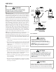
When opening valves with retainers, open each valve only until
the top of the stem is 1/8" from the retainer. To avoid loss of
refrigerant, DO NOT apply pressure to the retainer. When opening
valves without a retainer remove service valve cap and insert a
hex wrench into the valve stem and back out the stem by turning
the hex wrench counterclockwise. Open the valve until it contacts
the rolled lip of the valve body.
NOTE: These are not back-seating valves. It is not necessary to
force the stem tightly against the rolled lip.
After the refrigerant charge has bled into the system, open the
liquid service valve. The service valve cap is the secondary seal
for the valve and must be properly tightened to prevent leaks.
Make sure cap is clean and apply refrigerant oil to threads and
sealing surface on inside of cap. Tighten cap finger-tight and then
tighten additional 1/6 of a turn (1 wrench flat) to properly seat
the sealing surfaces.
EXPANSION VALVE SYSTEM
NOTE: Units matched with indoor coils equipped with non-
adjustable TXV should be charged by subcooling only.
NOTE: The TXV should NOT be adjusted at light load conditions
55º to 60ºF. Use the following guidelines and methods to check
unit operation and ensure that the refrigerant charge is within
limits. Charge the unit on low stage.
Units Equipped with Adjustable Expansion Valves
should be charged by Subcooling and
Superheat
adjusted only if necessary.
1. Purge gauge lines. Connect service gauge manifold to base-
valve service ports. Run the system in low stage at least 10
minutes to allow pressure to stabilize.
2. Temporarily install a thermometer on the liquid line at the
liquid line service valve and 4-6" from the compressor on the
suction line. Ensure the thermometer makes adequate con-
tact and is insulated for best possible readings. Use liquid
line temperature to determine subcooling and vapor tem-
perature to determine superheat.
3. Check subcooling and superheat. Systems with TXV applica-
tion should have a subcooling of 5 to 7°F and superheat of
7 to 9 °F.
a. If subcooling and superheat are low, adjust TXV to 7 to 9
ºF superheat, and then check subcooling.
NOTE: To adjust superheat, turn the valve stem clockwise to
increase and counter clockwise to decrease.
b. If subcooling is low and superheat is high, add charge to
raise subcooling to 5 to 7 °F then check superheat.
c. If subcooling and superheat are high, adjust TXV valve to
7 to 9 ºF superheat, then check subcooling.
d. If subcooling is high and superheat is low, adjust TXV valve
to 7 to 9 ºF superheat and remove charge to lower the
subcooling to 5 to 7 ºF.
NOTE: Do NOT adjust the charge based on suction pressure
unless there is a gross undercharge.
4. Disconnect manifold set, installation is complete.
SUBCOOLING FORMULA = SATURATED LIQUID TEMP. - LIQUID
LINE TEMP.
NOTE: Check the Schrader ports for leaks and tighten valve cores
if necessary. Install caps finger-tight.
HEAT PUMP - HEATING CYCLE
The proper method of charging a heat pump in the heat mode is
by weight with the additional charge adjustments for line size,
line length, and other system components. For best results on
outdoor units with TXVs, superheat should be 2-5°F at 4-6" from
the compressor. Make final charge adjustments in the cooling
cycle.
S-104 CHECKING COMPRESSOR EFFICIENCY
The reason for compressor inefficiency is broken or damaged
scroll flanks on Scroll compressors, reducing the ability of the
compressor to pump refrigerant vapor.
The condition of the scroll flanks is checked in the following
manner.