
Service Manual


SERVICING
115
1. Attach gauges to the high and low side of the system.
2. Start the system and run a "Cooling Performance Test.
If the test shows:
a.
Below normal high side pressure.
b. Above normal low side pressure.
c. Low temperature difference across coil.
d.
Low amp draw at compressor.
And the charge is correct. The compressor is faulty - replace the
compressor.
S-106 OVERFEEDING
Overfeeding by the expansion valve results in high suction
pressure, cold suction line, and possible liquid slugging of the
compressor.
If these symptoms are observed:
1. Check for an overcharged unit by referring to the cooling
performance charts in the servicing section.
2. Check the operation of the power element in the valve as
explained in S-110 Checking Expansion Valve Operation.
3. Check for restricted or plugged equalizer tube.
S-107 UNDERFEEDING
Underfeeding by the expansion valve results in low system
capacity and low suction pressures.
If these symptoms are observed:
1. Check for a restricted liquid line or drier. A restriction will
be indicated by a temperature drop across the drier.
2. Check the operation of the power element of the valve as
described in S-110 Checking Expansion Valve Operation.
S-108 SUPERHEAT
The expansion valves are factory adjusted to maintain 7 to 9
degrees superheat of the suction gas. Before checking the super-
heat or replacing the valve, perform all the procedures outlined
under Air Flow, Refrigerant Charge, Expansion Valve - Overfeed-
ing, Underfeeding. These are the most common causes for
evaporator malfunction.
CHECKING SUPERHEAT
Refrigerant gas is considered superheated when its temperature
is higher than the saturation temperature corresponding to its
pressure. The degree of superheat equals the degrees of tempera-
ture increase above the saturation temperature at existing pres-
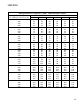
sure. See Temperature - Pressure Chart on following pages.
CAUTION
To prevent personal injury, carefully connect and
disconnect manifold gauge hoses. Escaping liquid
refrigerant can cause burns. Do not vent refrigerant
to atmosphere. Recover during system repair
or final unit disposal.
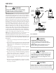
1. Run system at least 10 minutes to allow pressure to stabilize.
2. For best results, temporarily install a thermometer on the
liquid line at the liquid line service valve and 4-6" from the
compressor on the suction line. Ensure the thermometer
makes adequate contact and is insulated for best possible
readings. Use liquid line temperature to determine sub-
cooling and vapor temperature to determine superheat.
NOTE: An optional method is to locate the thermometer at the
suction line service valve. Ensure the thermometer makes
adequate contact and is insulated for best possible read-
ings.
3. Refer to the superheat table provided for proper system
superheat. Add charge to lower superheat or recover charge
to raise superheat.
Superheat Formula = Suct. Line Temp. - Sat. Suct. Temp.
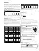
EXAMPLE:
a. Suction Pressure = 143
b. Corresponding Temp. °F. = 50
c. Thermometer on Suction Line = 61°F.
To obtain the degrees temperature of superheat, subtract 50.0
from 61.0°F.
The difference is 11° Superheat. The 11° Superheat would fall in
the ± range of allowable superheat.
S-109 CHECKING SUBCOOLING
Refrigerant liquid is considered subcooled when its temperature is
lower than the saturation temperature corresponding to its pressure.
The degree of subcooling equals the degrees of temperature decrease
below the saturation temperature at the existing pressure.
1. Attach an accurate thermometer or preferably a thermo-
couple type temperature tester to the liquid line as it leaves
the condensing unit.
2. Install a high side pressure gauge on the high side (liquid)
service valve at the front of the unit.
3. Record the gauge pressure and the temperature of the line.
4. Review the technical information manual or specification
sheet for the model being serviced to obtain the design
subcooling.