
Service Manual

SERVICING
93
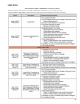
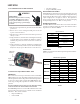
S-15 CHECKING CAPACITOR
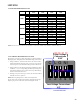
CAPACITOR, RUN
A run capacitor is wired across the auxiliary and main windings
of a single phase permanent split capacitor motor. The capaci-
tors primary function is to reduce the line current while greatly
improving the torque characteristics of a motor. This is accom-
plished by using the 90° phase relationship between the capaci-
tor current and voltage in conjunction with the motor windings,
so that the motor will give two phase operation when connected
to a single phase circuit. The capacitor also reduces the line
current to the motor by improving the power factor.
The line side of this capacitor is marked with "COM" and is wired
to the line side of the circuit.
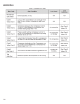
CAPACITOR, START
SCROLL COMPRESSOR MODELS
In most cases hard start components are not required on Scroll
compressor equipped units due to a non-replaceable check valve
located in the discharge line of the compressor. However, in
installations that encounter low lock rotor voltage, a hard start
kit can improve starting characteristics and reduce light dim-
ming within the home. Only hard start kits approved by Amana
®
brand or Copeland should be used. "Kick Start" and/or "Super
Boost" kits are not approved start assist devices.
The discharge check valve closes off high side pressure to the
compressor after shut down allowing equalization through the
scroll flanks. Equalization requires only about 1/2 second.
To prevent the compressor from short cycling, a Time Delay
Relay (Cycle Protector) has been added to the low voltabe
circuit.
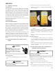
S-15A RESISTANCE CHECK USING A DIGITAL MULTI-
METER
WARNING
HIGH VOLTAGE!
Disconnect ALL power before servicing
or installing. Multiple power sources
may be present. Failure to do so may
cause property damage, personal injury
or death.
Check for Digital Test
1. Set the meter on Ohm range (Set it at lease 1000 Ohm
=1k).
WARNING
Discharge capacitor through a 20 to 30 OHM
resistor before handling.
WARNING
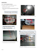
2. Connect the Meter leads to the Capacitor terminals.
3. Digital meter will show a reading momentarily (Figure 1).
Note the reading.
Figure 1 Figure 2
4. Reading will immediately return to the OL = (Open Line)
(Figure 2). Every attempt of Step 2 will show the same result
as was in step 4 and Step 5. This indicates that the capacitor
is good.
5. If there is no Change, then capacitor is dead and must be
replaced.
Check for Analog Meter
A. Good Condition - indicator swings to zero and slowly
returns to infinity. (Start capacitor with bleed resistor will
not return to infinity. It will still read the resistance of the
resistor).
B. Shorted - indicator swings to zero and stops there - replace.
C. Open - no reading - replace. (Start capacitor would read
resistor resistance.)
S-15BCAPACITANCE CHECK USING A DIGITAL MULTI-
METER (IN CAPACITANCE MODE)
WARNING
Discharge capacitor through a 20 to 30 OHM
resistor before handling.
WARNING
NOTE: You can do this test with a multi-meter if you have a
Capacitance meter on your multi-meter.
1. Remove the capacitor from the circuit.
2. Now Select "Capacitance" on your multi-meter.
3. Now connect the capacitor terminals to the multi-meter
leads.
4. If the reading is near to the actual value of the capacitor (i.e.
the printed value on the capacitor). The capacitor is good.