
Service Manual

SERVICING
95
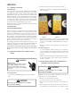
S-16CCHECKING ECM MOTOR WINDINGS
WARNING
HIGH VOLTAGE!
Disconnect ALL power before servicing
or installing. Multiple power sources
may be present. Failure to do so may
cause property damage, personal injury
or death.
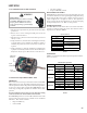
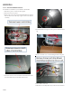
1. Disconnect the 5-pin and the 16-pin connectors from the ECM
power head.
2. Remove the 2 screws securing the ECM power head and
separate it from the motor.
3. Disconnect the 3-pin motor connector from the power head
and lay it aside.
4. Using an ohmmeter, check the motor windings for continuity
to ground (pins to motor shell). If the ohmmeter indicates
continuity to ground, the motor is defective and must be
replaced.
5. Using an ohmmeter, check the windings for continuity (pin
to pin). If no continuity is indicated, the thermal limit (over
load) device may be open. Allow motor to cool and retest.
16-pin
connector
5-pin
connector
3-pin motor
connector
S-16DECM CFM ADJUSTMENTS MBE / AEPF
MBE MOTOR
This section references the operation characteristics of the MBE/
AEPF models motor only. The ECM control board is factory set
with the dipswitch #4 in the “ON” position and all other dipswitches
are factory set in the “OFF” position. When MBE/AEPF are used
with 2-stage cooling units, dipswitch #4 should be in the "OFF"
position.
For most applications, the settings are to be changed according
to the electric heat size and the outdoor unit selection.
The MBE/AEPF products use a General Electric ECM
TM
motor. This
motor provides many features not available on the traditional
PSC motor. These features include:
• Improved Efficiency
• Constant CFM
• Soft Start and Stop
• Improved Humidity Control
MOTOR SPEED ADJUSTMENT
Each ECM™ blower motor has been preprogrammed for operation
at 4 distinct airflow levels when operating in Cooling/Heat Pump
mode or Electric Heat mode. These 4 distinct levels may also be
adjusted slightly lower or higher if desired. The adjustment
between levels and the trim adjustments are made by changing
the dipswitch(s) either to an "OFF" or "ON" position.
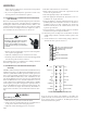
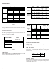
DIPSWITCH FUNCTIONS
The MBE / AEPF air handler motors have an electronic control that
contains an eight (8) position dip switch. The function of these
dipswitches are shown in Table 1.
Dipswitch
Number
1
2
3N/A
4 Indoor Thermostat
5 Cooling & Heat
6 Pump CFM
7
8
Function
Electric Heat
CFM Tri m Adjust
Dipswitch Functions
Table 1
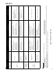
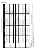
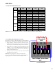
CFM DELIVERY
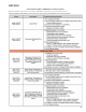
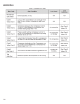
Tables 2, 3, 5 and 6 show the CFM output for dipswitch combina-
tions 1-2, and 5-6.
Model Switch 1 Switch 2 CFM
OFF
OFF
1,200
ON
OFF
1,000
OFF
ON
800
ON ON 600
OFF
OFF
1,600
ON
OFF
1,400
OFF
ON
1,200
ON ON 1,000
OFF
OFF
2,000
ON OFF 1,800
OFF ON 1,600
ON ON 1,200
MBE1200
MBE1600
MBE2000
Electric Heat Operation
Table 2