
Instructions / Assembly


23
When the furnace is used in connection with a cooling unit, the
furnace should be installed in parallel with or on the upstream
side of the cooling unit to avoid condensation in the heating
element. With a parallel flow arrangement, the dampers or other
means used to control the flow of air must be adequate to
prevent chilled air from entering the furnace and, if manually
operated, must be equipped with means to prevent operation of
either unit unless the damper is in the full heat or cool position.
When the furnace is installed without a cooling coil, it is rec-
ommended that a removable access panel be provided in the
outlet air duct. This opening shall be accessible when the fur-
nace is installed and shall be of such a size that the heat
exchanger can be viewed for visual light inspection or such that
a sampling probe can be inserted into the airstream. The ac-
cess panel must be made to prevent air leaks when the furnace
is in operation.
NOTE: In a horizontal installation the air conditioning coil
must be adequately supported by proper brackets and
supports. Inadequate coil support can result in furnace cabinet
distortion and air leakage.
When the furnace is heating, the temperature of the return air
entering the furnace must be between 55°F and 100°F.
When a furnace is installed so that supply ducts carry air cir-
culated by the furnace to areas outside the space containing
the furnace, the return air shall also be handled by a duct sealed
to the furnace casing and terminating outside the space con-
taining the furnace.
CHECKING D UCT S TATIC
Refer to your furnace rating plate for the maximum ESP (exter-
nal duct static) rating.
Total external static refers to everything external to the furnace
cabinet. Cooling coils, filters, ducts, grilles, registers must all
be considered when reading your total external static pres-
sure. The supply duct pressure must be read between the fur-
nace and the cooling coil. This reading is usually taken by
removing the “A” shaped block off plate from the end on the
coil; drilling a test hole in it and reinstalling the block off plate.
Take a duct static reading at the test hole. Tape up the test
hole after your test is complete. The negative pressure must be
read between the filter and the furnace blower.
Too much external static pressure will result in insufficient air
that can cause excessive temperature rise. This can cause
limit switch tripping and heat exchanger failure.
To determine total external duct static pressure, proceed as
follows;
1. With clean filters in the furnace, use a draft gauge
(inclined manometer) to measure the static pressure of
the return duct at the inlet of the furnace. (Negative
Pressure)
2. Measure the static pressure of the supply duct. (Positive
Pressure)
3. The difference between the two numbers is .4” w.c.
Example:
static reading from return duct = -.1" w.c.
static reading from supply duct = .3" w.c.
total external static pressure on this system = .4" w.c.
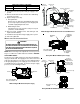
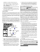
NOTE: Both readings may be taken simultaneously and read
directly on the manometer if so desired. If an air conditioner
coil or Electronic Air Cleaner is used in conjunction with the
furnace, the readings must also include theses components,
as shown in the following drawing.
4. Consult proper tables for the quantity of air.
If the total external static pressure exceeds the maximum listed
on the furnace rating plate, check for closed dampers, regis-
ters, undersized and/or oversized poorly laid out duct work.
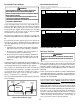
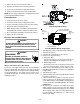
Checking Static Pressure
(80% Furnace Shown, 90% Similar)
FILTERS - READ T HIS S ECTION B EFORE I NSTALLING THE
RETURN A IR DUCTWORK
Filters must be used with this furnace. Discuss filter mainte-
nance with the building owner. Filters do not ship with this
furnace, but must be provided by the installer. Filters must com-
ply with UL900 or CAN/ULCS111 standards. If the furnace is
installed without filters, the warranty will be voided.
NOTE: An undersized opening will cause reduced airflow. The
bottom return is set up as a knock out.
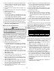
UPRIGHT I NSTALLATIONS
Depending on the installation and/or customer preference, dif-
fering filter arrangements can be applied. Filters can be in-
stalled in the central return register or a side panel external
filter rack kit (upflows), or the ductwork above a downflow fur-
nace. As an alternative, a media air filter or electronic air cleaner
can be used as the primary filter.