
Instructions / Assembly


27
Natural Gas Minimum: 4.5" w.c. Maximum: 10.0" w.c.
Propane Gas Minimum: 11.0" w.c. Maximum: 13.0" w.c.
INLET GAS SUPPLY PRESSURE
9. Turn OFF all electrical power and gas supply to the
system.
10. Remove the manometer hose from the hose barb fitting
or inlet pressure Tap.
11. Replace inlet pressure tap:
a. Honeywell valve:
Remove the 1/8” NPT hose barb fitting from the inlet
pressure tap. Replace the inlet pressure Tap plug and
seal with a high quality thread sealer.
b. White-Rodgers valve:
Turn inlet pressure test screw in to seal pressure port
(clockwise, 7 in-lb minimum).
12. Retest for leaks. If bubbles form, shut down gas and
repair leaks immediately.
13. Turn ON electrical power and gas supply to the system.
14. Turn valve switch ON.
MODELS USING TWO STAGE GAS VALVES
T
O
PREVENT
UNRELIABLE
OPERATION
OR
EQUIPMENT
DAMAGE
,
THE
GAS
MANIFOLD
PRESSURE
MUST
BE
AS
SPECIFIED
ON
THE
UNIT
RATING
PLATE
. O
NLY
MINOR
ADJUSTMENTS
SHOULD
BE
MADE
BY
ADJUSTING
THE
GAS
VALVE
PRESSURE
REGULATOR
.
CAUTION
NOTE: When removing a valve adjustment screw or a pressure
Tap, use a T-25 Torx or 3/616” flathead screwdriver. DO NOT
USE POWER TOOLS.
The line pressure supplied to the gas valve must be within the
range specified below. The supply pressure can be measured
at the gas valve inlet pressure Tap or at a hose fitting installed
in the gas piping drip leg. The supply pressure must be mea-
sured with the burners operating. To measure the gas supply
pressure, use the following procedure.
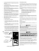
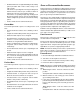
INLET OUTLET
Gas Valve On/Off
Selector Switch
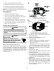
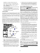
White-Rodgers Model 36J54 (Two-Stage)
Inlet
Pressure
TAP
Low Fire
Re
g
ulator
Adjust
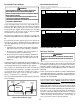
M
a
n
o
m
e
t
e
r
M
a
n
o
m
e
t
e
r
H
o
s
e
High Fire Regulator
Adjust
Re
g
ulator
Vent
Outlet
Pressure Boss
Open t
o
Atmosphere
O
n
/
O
f
f
S
w
i
t
c
h
H
i
g
h
F
i
r
e
C
o
i
l
T
e
r
m
i
n
a
l
(
H
I
)
C
o
a
x
i
a
l
C
o
i
l
T
e
r
m
i
n
a
l
(
M
)
Common
Terminal(C)
White-Rodgers Model 36J54 Connected to Manometer
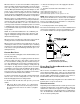
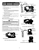
Gas Valve On/Off
Selector Switch
Regulator
Vent
High Fire
Regulator
Adjust
Low Fire
Regulator
Adjust
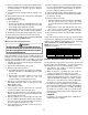
Honeywell Model VR9205 (Two-Stage)
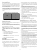
i
M
a
n
o
m
e
t
e
r
M
a
n
o
m
e
t
e
r
H
o
s
e
Common
Terminal
(
C
)
Hi
g
h Fire Coil
Terminal (HI)
Low Fire Coil
Terminal (LO)
Inlet Pressure Tap
1/8 NPT
O
p
e
n
t
o
A
t
m
o
s
p
h
e
r
e
Outlet Pressure Tap
1/8 NPT
Honeywell Model VR9205 Connected to Manometer