
Instructions / Assembly


28
1. Turn OFF gas to furnace at the manual gas shutoff valve
external to the furnace.
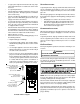
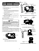
2. Connect a calibrated water manometer (or appropriate
gas pressure gauge) at either the gas valve inlet pressure
Tap or the gas piping drip leg. See Honeywell gas valve
figure or White-Rodgers gas valve figure for location of
inlet pressure Tap.
NOTE: If measuring gas pressure at the drip leg or Honeywell
gas valve, a field-supplied hose barb fitting must be installed
prior to making the hose connection. If using the inlet pressure
Tap on the White-Rodgers gas valve, then use the 36G Valve
Pressure Check Kit, Goodman Part No. 0151K00000S.
3. Turn ON the gas supply and operate the furnace and all
other gas consuming appliances on the same gas supply
line.
4. Measure furnace gas supply pressure with burners firing.
Supply pressure must be within the range specified in
the Inlet Gas Supply Pressure table.
Natural Gas Minimum: 4.5" w.c. Maximum: 10.0" w.c.
Propane Gas Minimum: 11.0" w.c. Maximum: 13.0" w.c.
INLET GAS SUPPLY PRESSURE
If supply pressure differs from table, make the necessary ad-
justments to pressure regulator, gas piping size, etc., and/or
consult with local gas utility.
5. Turn OFF gas to furnace at the manual shutoff valve and
disconnect manometer. Reinstall plug before turning on
gas to furnace.
6. Turn OFF any unnecessary gas appliances stated in
step 3.
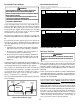
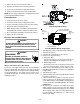
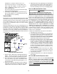
Gas Line
Gas
Shutoff
Valve
Gas Line
To Furnace
Drip Leg Cap
With Fitting
Manometer Hose
Measuring Inlet Gas Pressure (Alt. Method)
GAS MANIFOLD P RESSURE MEASUREMENT AND ADJUSTMENT
T
O
PREVENT
UNRELIABLE
OPERATION
OR
EQUIPMENT
DAMAGE
,
THE
GAS
MANIFOLD
PRESSURE
MUST
BE
AS
SPECIFIED
ON
THE
UNIT
RATING
PLATE
. O
NLY
MINOR
ADJUSTMENTS
SHOULD
BE
MADE
BY
ADJUSTING
THE
GAS
VALVE
PRESSURE
REGULATOR
.
CAUTION
HIGH VOLTAGE !
D
ISCONNECT
ALL
POWER
BEFORE
SERVICING
OR
INSTALLING
THIS
UNIT
. M
ULTIPLE
POWER
SOURCES
MAY
BE
PRESENT
. F
AILURE
TO
DO
SO
MAY
CAUSE
PROPERTY
DAMAGE
,
PERSONAL
INJURY
OR
DEATH
.
WARNING
MODELS USING SINGLE STAGE GAS VALVES
This valve is shipped from the factory with the regulator preset
(see control label).
Consult the appliance rating plate to ensure burner manifold
pressure is as specified. If another outlet pressure is required,
follow these steps.
1. Turn OFF gas to furnace at the manual gas shutoff valve
external to the furnace.
2. Turn OFF all electrical power to the system.
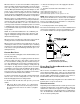
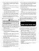
3. Outlet pressure tap connections:
a. Honeywell valve:
Remove the outlet pressure Tap plug. Install an 1/8”
NPT hose barb fitting into the outlet pressure tap.
b. White-Rodgers valve:
Back outlet pressure test screw (outlet pressure Tap)
out one turn (counterclockwise, not more than one
turn).
4. Attach a hose and manometer to the outlet pressure
barb fitting (Honeywell valve) or outlet pressure Tap (White-
Rodgers valve).
5. Turn ON the gas supply.
6. Turn ON power and close thermostat “R” and “W”
contacts to provide a call for heat.
7. Using a leak detection solution or soap suds, check for
leaks at outlet pressure Tap plug (Honeywell valve) or
screw (White-Rodgers valve). Bubbles forming indicate
a leak. SHUT OFF GAS AND REPAIR ALL LEAKS
IMMEDIATELY!
8. Measure the gas manifold pressure with burners firing.
Adjust manifold pressure using the Manifold Gas
Pressure table shown below.
Manifold Gas Pressure
Natural Gas 3.5" w.c.
Propane Gas 10.0" w.c.