
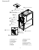
Instructions / Assembly


31
As shipped, the circulator blower fan will remain on for 150
seconds after the gas valve closes. When a call for cooling
occurs, the circulator fan comes on and remains on for 45 sec-
onds after the call for cooling ends. During normal heating op-
eration, the circulator fan will come on approximately 34 sec-
onds after the gas valve opens.
O
N
O
F
F
O
N
O
F
F
1
150
SECOND
DELAY
100
SECOND
DELAY
1
Switch viewed in an upflow installation.
Adjustment Switch
SETTING F URNACE OPERATING M ODE (GDH8, GME8,
*MH8, AMEH8 AND ADSH8 MODELS ONLY)
This furnace is designed to operate with either a single gas
input rate or with two discrete gas input rates. The Mode
DIP switch is used to select the single gas input rate or two
discrete input rates.
Setting the Mode switch to “1 STG” forces the furnace to oper-
ate at the furnace’s highest input rate only. Operation is as
described under Sequence of Operation (Integrated Ignition
Control) – Mode DIP Switch is set to “1 STG” position.
Setting the Mode switch to “2 STG” allows the furnace to oper-
ate at the furnace’s highest input AND at an input rate that is
75% of the highest input rate. For this mode of operation, the
furnace operates at the low input rate for a pre-determined
time period then steps to the high input rate. Operation is as
described under Sequence of Operation (Integrated Ignition
Control) – Mode DIP Switch is set to “2 STG” position.
The time period is determined by the 2
nd
Stg Dly DIP switch.
Setting the 2
nd
Stg Dly DIP switch to 5 minutes fixes the
delay period at 5 minutes. Setting the 2
nd
Stg Dly DIP
switch to Auto enables an algorithm that calculates a delay
period based on the heating cycle time and the total cycle
time. The delay period can range from 1 minute to 12
minutes.
5 MIN
OFF
ON
1 STG
AUTO
2 STG
M
2
ND
STG DLY
O
PERATIONAL
C
HECKS
WARNING
T
O AVOID PERSONAL INJURY OR DEATH, DO NOT REMOVE ANY INTERNAL
COMPARTMENT COVERS OR ATTEMPT ANY ADJUSTMENT.
E
LECTRICAL
COMPONENTS ARE CONTAINED IN BOTH COMPARTMENTS.
C
ONTACT A
QUALIFIED SERVICE AGENT AT ONCE IF AN ABNORMAL FLAME APPEARANCE
SHOULD DEVELOP.
BURNER FLAME
The burner flames should be inspected with the burner com-
partment door installed. Flames should be stable, quiet, soft,
and blue (dust may cause orange tips but they must not be
yellow). Flames should extend directly outward from the burn-
ers without curling, floating, or lifting off. Flames must not
impinge on the sides of the heat exchanger firing tubes.
Burner Flame
AUXILIARY L IMIT C ONTROL
Auto reset limits are located on or near the blower. To access
this auxiliary limit, disconnect the electrical power and remove
the blower door. The auxiliary limit control is designed to pre-
vent furnace operation in case of main blower failure on hori-
zontal installations. It may also open if the power supply is
interrupted while the furnace is firing. The auxiliary limit control
is suitable for both horizontal right and horizontal left installa-
tions. Regardless of airflow direction, it does not need to be
relocated.
T
O
AVOID
PERSONAL
INJURY
OR
DEATH
,
DO
NOT
REMOVE
ANY
INTERNAL
COMPARTMENT
COVERS
OR
ATTEMPT
ANY
ADJUSTMENT
.
E
LECTRICAL
COMPONENTS
ARE
CONTAINED
IN
BOTH
COMPARTMENTS
.
C
ONTACT
A
QUALIFIED
SERVICE
AGENT
AT
ONCE
IF
AN
ABNORMAL
FLAME
APPEARANCE
SHOULD
DEVELOP
.
WARNING