
Installation Guide


3
Do NOT let refrigerant lines come in direct contact with plumb-
ing, ductwork, floor joists, wall studs, floors, and walls. When
running refrigerant lines through a foundation or wall, openings
should allow for sound and vibration absorbing material to be
placed or installed between tubing and foundation. Any gap
between foundation or wall and refrigerant lines should be filled
with a pliable silicon-based caulk, RTV or a vibration damping
material. Avoid suspending refrigerant tubing from joists and
studs with rigid wire or straps that would come in contact with
the tubing. Use an insulated or suspension type hanger. Keep
both lines separate and always insulate the suction line.
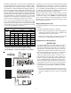
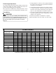
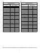
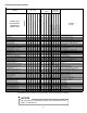
These sizes are recommended for line lengths of 79 feet or
less to obtain optimum performance. For alternate line sizing
options or runs of more than 79 feet, refer to Remote Cooling
Service Manual or TP-107 Long Line Set Application R-410A
or contact your distributor for assistance.
Cond
Unit
Tons Suct Liq Suct Liq Suct Liq
1 1/2 5/8 1/4 3/4 3/8 3/4 3/8
2 5/81/43/43/83/43/8
2 1/2 5/8 1/4 3/4 3/8 7/8 3/8
3 3/4 3/8 7/8 3/8 1 1/8 3/8
3 1/2 7/8 3/8 1 1/8 3/8 1 1/8 3/8
4 7/8 3/8 1 1/8 3/8 1 1/8 3/8
5 7/8 3/8 1 1/8 3/8 1 1/8 3/8
Line Diameter (In. OD)
RECOMMENDED INTERCONNECTING TUBING (Ft)
0-24 25-49 50-79*
* Lines greater than 79 feet in length or vertical elevation
changes more than 50 feet
refer to the Remote Cooling
Service Manual or contact your distributor for assistance.
Insulation is necessary to prevent condensation from forming
and dropping from the suction line. Armflex (or satisfactory
equivalent) with 3/8” min. wall thickness is recommended. In
severe conditions (hot, high humidity areas) 1/2” insulation may
be required. Insulation must be installed in a manner which
protects tubing from damage and contamination.
Where possible, drain as much residual compressor oil from
existing systems, lines, and traps; pay close attention to low
areas where oil may collect. NOTE: If changing refrigerant
types, ensure the indoor coil and metering device is compat-
ible with the type of refrigerant being used; otherwise, the in-
door coil must be replaced.
Burying Refrigerant Lines
If burying refrigerant lines can not be avoided, use the following
checklist.
1. Insulate liquid and suction lines separately.
2. Enclose all underground portions of the refrigerant lines
in waterproof material (conduit or pipe) sealing the ends
where tubing enters/exits the enclosure.
3. If the lines must pass under or through a concrete slab,
ensure lines are adequately protected and sealed.
Refrigerant Line Connections
IMPORTANT
To avoid overheating the service valve, TXV valve, or filter
drier while brazing, wrap the component with a wet rag, or
use a thermal heat trap compound. Be sure to follow the
manufacturer’s instruction when using the heat trap
compound. Note: Remove Schrader valves from service
valves before brazing tubes to the valves. Use a brazing
alloy of 2% minimum silver content. Do not use flux.
Torch heat required to braze tubes of various sizes is
proportional to the size of the tube. Tubes of smaller size
require less heat to bring the tube to brazing temperature
before adding brazing alloy. Applying too much heat to
any tube can melt the tube. Service personnel must use
the appropriate heat level for the size of the tube being
brazed. Note: The use of a heat shield when brazing is
recommended to avoid burning the serial plate or the finish
on the unit.
1. The ends of the refrigerant lines must be cut square, de-
burred, cleaned, and be round and free from nicks or dents.
Any other condition increases the chance of a refrigerant
leak.