
Instructions / Assembly


13
Communication mode use
This feature can be activated or deactivated through the thermostat user menus. An auxiliary alarm switch must be
normally closed and open when the base pan’s water level
in the evaporator coil reaches a particular level. The control
will respond by turning off the outdoor compressor and dis-
play the proper fault codes. If the switch is detected closed
for 30 seconds, normal operation resumes and the error
message will be removed.
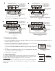
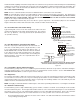
16 AVPTC Motor Orientation
If the unit is in the upflow position, there is no need to rotate
the motor. If the unit is in the downflow position, loosen
motor mount and rotate motor as shown in the AVPTC Mo-
tor Orientation figure below. Be sure motor is oriented with
the female connections on the casing down. If the motor is
not oriented with the connections down, water could collect
in the motor and may cause premature failure.
FEMALE CONNECTIONS
SIDE VIEW
W
A
RNING
SOFTW
A
RE VER.
TOP
FRONT VIEW
AVPTC Motor Orientation
Figure 20
COM
TH
TR
DE
CAS
HUM
O
R
2
1
C
2
1
ST4
ST3
ST2
ST1
3A
C
Y2
24VAC
FUSE
W1W2
R
C
G
W1
W2
Y1
3
2
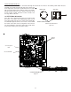
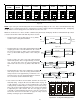
Dip Switches
Green CFM LED
Seven Segment
LED
Auxiliary
Alarms
Communicating Board
Figure 21