
Instructions / Assembly


15
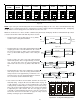
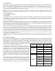
• Profile A provides only an OFF delay of one (1) minute
at 100% of the cooling demand airflow.
• Profile B ramps up to full cooling demand airflow by first
stepping up to 50% of the full demand for 30 seconds.
The motor then ramps to 100% of the required airflow.
A one (1) minute OFF delay at 100% of the cooling air-
flow.
• Profile C ramps up to 82% of the full cooling demand
airflow and operates there for approximately 7 1/2 min-
utes. The motor then steps up to the full demand air-
flow. Profile C also has a one (1) minute 100% OFF de-
lay.
• Profile D ramps up to 50% of the demand for 1/2 minute,
then ramps to 82% of the full cooling demand airflow
and operates there for approximately 7 1/2 minutes. The
motor then steps up to the full demand airflow. Profile D
has a 1/2 minute at 50% airflow OFF delay.
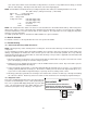
7. If an electric heater kit has been installed, determine the heater kilo-
watt (kW) rating. Using the Electric Heat Airflow table on page 16,
set dip switches 9, 10, and 11 for the installed heater. The adjust
setting (already established by the cooling speed selection) also ap-
plies to the electric heater kit airflow. Thus, the electric heater airflow
is adjusted by the same amount. This does not apply to systems
setup with a communicating thermostat. See Set-Up section in the
AIR HANDLER ADVANCED FEATURES MENU on page 22. Verify selected
CFM by counting the green CFM LED blinks.
NOTE: Upon start up in communicating mode the circuit board may display an “Ec” error. This is an indication that the dip
switches on the control board need to be configured in accordance with the Electric Heating Airflow Table. Configuring
the dip switches and resetting power to the unit will clear the error code.
Within the thermostat user menu, CTK0* communicating thermostat will display 20 kW for OFF-OFF-ON dip switch
selection and 21 kW for OFF-OFF-OFF dip switch selection.
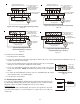
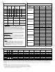
S9
S10
OFF OFF OFF OFFON ON ON ON
21 kW* or
25 kW*
19 kW or
20 kW
Electric Heating Airflow (*indicates factory setting)
15 kW 10 kW
OFF OFF OFF OFFON ON ON ON
8 kW 6 kW 5 kW 3 kW
S11
S9
S10
S11
S9
S10
S11
S9
S10
S11
S9
S10
S11
S9
S10
S11
S9
S10
S11
S9
S10
S11
Figure 25
OFF
100% CFM 100% CFM
1 min
OFF
Figure 26
50% CFM
1/2 min
100% CFM
100% CFM
1 min
OFF
OFF
Figure 27
100% CFM
OFF
OFF
Figure 28
OFF
OFF
Figure 29
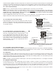
S5
S6
S5
S6
S5
S6
S5
S6
OFF OFF OFF OFFON ON ON ON
Tap A* Tap B Tap C Tap D
Dip Switches - Cooling Airflow Ramping Profiles
Figure 30