
Instructions / Assembly


17
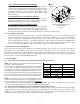
HTR kW 9 10 11 AVPTC24B14A AVPTC30C14A AVPTC36C14A AVPTC48C14A AVPTC42D14A† AVPTC48D14A†† AVPTC60D14A†††
3 ON ON ON 550 600 N
R
N
R
850** N
R
N
R
5 ON ON OFF 650 700 850 850 1250 1250 1250
6 ON OFF ON 700 750 900 900 1300 1300 1300
8 ON OFF OFF 800 875 1000 1000 1500 1500 1500
10 OF
F
ON ON 850 950 1200 1200 1550 1550 1550
15 OF
F
ON OFF N
R
N
R
1440 1440 1720 1720 1780
19* N
R
N
R
1500 1500 N
R
N
R
N
R
20 N
R
N
R
1500 1500 1800 1815 1850
21 or 25* OF
F
OFF OFF N
R
N
R
N
R
N
R
N
R
1850 1850
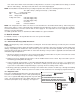
ELECTRIC HEAT AIRFLOW TABLE
OFF OFF ON
Note: Airflow data shown applies to the electric heat only in either legacy mode or communicating mode operationNR - Not rated* Within thermostat
user menu, CTK0* communicating thermostat will display 20 kW for OFF-OFF-ON dip switch selection and 21 kW for OFF-OFF-OFF dip switch
selection.
† For match up with a 2 ton outdoor unit: Heater kit application shall not exceed 10 kW. Airflow for 5 kW up to 10 kW heater kits shall be set to 850 cfm speed tap of
ON-ON-ON.
†† For match up with a 3 ton outdoor unit: Heater kit application shall not exceed 15 kW.
Airflow for 5 kW up to 15 kW heater kits shall be set to 1300 cfm speed tap of ON-OFF-ON.
††† For match up with a 3.5 ton outdoor unit: Heater kit application shall not exceed 20 kW.
Airflow for 5 kW up to 20 kW heater kits shall be set to 1500 cfm speed tap of ON-OFF-OFF
** 3 kW heater kit is not applicable for this indoor application.
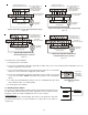
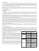
B ------- 30 sec/50% 60 sec/100%
Speed Selection Dip Switches
A OFF OFF OFF OFF OFF OFF
TAP S1 S2 S3 S4 S5 S6
B ON OFF ON OFF ON OFF
A ------- -------- 60 sec/100%
To
set Airflow:
(1) Select model and desired High Stage Cooling
Airflow. Determine the corresponding tap (A, B, C, D). Set dip
switches S1 and S2 to the appropriate ON / OFF positions.
(2) Select model and installed electric heater size. Set dip
switches S9, S10, and S11 to the appropriate ON / OFF positions.
(3) If airflow adjustment is required set Trim Enable Switch to
S8
ON (OFF = 0% Trim) and set S3 and S4 to appropriate ON / OFF
positions. Tap A is +5%,Tap B is -5%, Tap C is +10%, Tap D is
-10%.
D ON ON ON ON ON ON
Cool Adjust Profile
Selection Selection Selection
Switches Switches Switches
Notes:
1. Airflow data shown applies to legacy mode operation only.
For a fully communicating system, please see the outdoor
unit's installation instructions for cooling and heat pump
airflow data. See
ComfortNet System-Airflow Consideration
section for details.
2. Airflow blink codes are approximations of actual airflow.
Profiles Pre-Run Short-Run OFF Delay
C OFF ON OFF ON OFF ON
C ------- 7.5 min/82% 60 sec/100%
D 30 sec/50% 7.5 min/82% 30 sec/50%
To
Set Comfort
mode:
Select desired Comfort Mode Profile (see
profiles above). Set dip switches S5 and S6 to appropriate ON /
OFF positions.
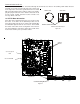
Dehumidification:
To enable, set dip switch S7 to ON. Cooling
airflow will be reduced to 85% of nominal value during cool call
when Dehum command is present. To disable, set S7 to OFF.
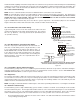
Continuous
Fan
Speed:
Use dip switches S12 and S13 to select
one of 4 continuous fan speeds, Tap A is 25%. Tap B is 50%, Tap
C is 75%, Tap D is 100%.
Continuous
Fan
Speed
S12
S13
OFF
ON
OFF
ON
OFF
OFF
ON
ON
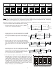
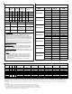
NOTE: Airflow blink codes are approximations of actual airflow. Airflows provided
are at 0.3 static.
Model Speed tap
Low stage
(CFM)
High stage
(CFM)
A
410 610
B
565 835
C
660 970
D
765 1125
A
440 610
B
605 835
C
740 1020
D
885 1225
A
500 725
B
700 1000
C
930 1330
D
1120 1600
A
500 725
B
700 1000
C
930 1330
D
1120 1600
A
560 800
B
765 1090
C
995 1420
D
1225 1750
A
900 1350
B
1035 1550
C
1140 1700
D
1200 1800
A
1210 1610
B
1365 1815
C
1450 1920
D
1525 2025
AVPTC48D14**
AVPTC60D14**
Cooling/Heat Pump Airflow Table
AVPTC24B14**
AVPTC30C14**
AVPTC36C14**
AVPTC48C14**
AVPTC42D14**