
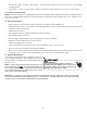
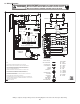
Instructions / Assembly

22
LED LED
Status
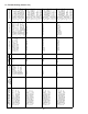
Indication Possible Causes Corrective Action(s) Notes & Cautions
Red
Communications
LED
Off
• Normal condition • None • None • None
1 Flash
• Communications
Failure
• Communications
Failure
• Depress Learn Button
• Verify that bus BIAS
and TERM
dipswitches are in the
ON position.
• Depress once
quickly for a power-
up reset
• Depress and hold
for 2 seconds for
an out-of-box reset
2 Flashes
• Out-of-box reset • Control power up
• Learn button
depressed
• None • None
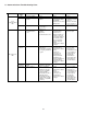
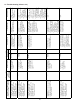
Green Receive
LED
Off
• No power
• Communications
error
• No power to air
handler
• Open fuse
• Communications error
• Check fuses and
circuit breakers;
replace/reset
• Replace blown fuse
• Check for shorts in
low voltage wiring in
air handler/system
• Reset network by
depressing learn
button
• Check data 1/ data 2
voltages
• Turn power OFF
prior to repair
1 Steady
Flash
• No network found • Broken/ disconnected
data wire(s)
• Air handler is installed
as a legacy/ traditional
system
• Check
communications
wiring (data 1/ data 2
wires)
• Check wire
connections at
terminal block
• Verify air handler
installation type
(legacy/ traditional or
communicating)
• Check data 1/ data 2
voltages
• Turn power OFF
prior to repair
• Verify wires at
terminal blocks are
securely twisted
together prior to
inserting into
terminal block
• Verify data1 and
data voltages as
described above
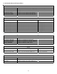
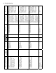
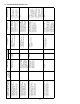
Rapid
Flashing
• Normal network
traffic
• Control is “talking” on
network as expected
• None • None
On Solid
• Data 1/ Data 2
miss-wire
• Data 1 and data 2
wires reversed at air
handler, thermostat,
or CT™ compatible
outdoor AC/HP
• Short between data 1
and data 2 wires
• Short between data 1
or data 2 wires and R
(24VAC) or C (24VAC
common)
• Check
communications
wiring (data 1/ data 2
wires)
• Check wire
connections at
terminal block
• Check data 1/ data 2
voltages
• Turn power OFF
prior to repair
• Verify wires at
terminal blocks are
securely twisted
together prior to
inserting into
terminal block
• Verify data1 and
data voltages as
described above
23 Communications Troubleshooting Chart