
Installations Instructions

10
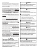
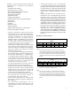
Installations must adhere to the clearances to combustible ma-
terials to which this furnace has been design certified. The
minimum clearance information for this furnace is provided on
the unit’s clearance label. These clearances must be perma-
nently maintained. Clearances must also accommodate an
installation’s gas, electrical, and drain trap and drain line con-
nections.
NOTE: In addition to the required clearances to combustible
materials, a minimum of 24 inches service clearance must be
available in front of the unit.
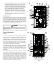
TOP
BOTTOM
SIDE SIDE SIDE
TOP
BOTTOM
Upflow Counterflow Horizontal
Figure 3
EXISTING FURNACE REMOVAL
NOTE: When an existing furnace is removed from a venting
system serving other appliances, the venting system may be
too large to properly vent the remaining attached appliances.
The following vent testing procedure is reproduced from
the American National Standard/ National Standard of
Canada for Gas-Fired Central Furnaces ANSI Z21. 4, CSA-
2.3 latest edition Section 1. 23. 1.
The following steps shall be followed with each appliance
connected to the venting system placed in operation, while
any other appliances connected to the venting system are
not in operation:
1. Seal any unused openings in the venting system;
2. Inspect the venting system for proper size and hori-
zontal pitch, as required by the National Fuel Gas Code,
ANSI Z223.1 or the Natural Gas and Propane Installa-
tion Code, CSA B149.1-15 and these instructions. De-
termine that there is no blockage or restriction, leak-
age, corrosion and other deficiencies which could cause
an unsafe condition.
3. As far as practical, close all building doors and win-
dows and all doors between the space in which the
appliance(s) connected to the venting system are lo-
cated and other spaces of the building.
4. Close fireplace dampers.
5. Turn on clothes dryers and any appliance not connected
to the venting system. Turn on any exhaust fans, such
as range hoods and bathroom exhausts, so they shall
operate at maximum speed. Do not operate a summer
exhaust fan.
6. Follow the lighting instructions. Place the appliance be-
ing inspected in operation. Adjust thermostat so appli-
ance shall operate continuously.
7. Test for spillage from draft hood appliances at the draft
hood relief opening after 5 minutes of main burner op-
eration. Use the flame of a match or candle.
8. If improper venting is observed during any of the above
tests, the venting system must be corrected in accor-
dance with the National Fuel Gas Code ANSI Z223.1/
NFPA 54 and/or National Gas and Propane Installation
Code CSA B149.1-15.
9. After it has been determined that each appliance con-
nected to the venting system properly vents when
tested as outlined above, return doors, windows, ex-
haust fans, fireplace dampers and any other gas burn-
ing appliance to their previous conditions of use.
If resizing is required on any portion of the venting system,
use the appropriate table in Appendix G in the latest edition
of the National Fuel Gas Code ANSI Z223.1 and/or
CSA B149.1-15 Installation Codes.
THERMOSTAT LOCATION
The thermostat should be placed approximately five feet
from the floor on a vibration-free, inside wall in an area
having good air circulation. Do not install the thermostat
where it may be influenced by any of the following:
• Drafts, or dead spots behind doors, in corners, or
under cabinets.
• Hot or cold air from registers.
• Radiant heat from the sun.
• Light fixtures or other appliances.
• Radiant heat from a fireplace.
• Concealed hot or cold water pipes, or chimneys.
• Unconditioned areas behind the thermostat, such
as an outside wall.
Consult the instructions packaged with the thermostat for
mounting instructions and further precautions.
C
OMBUSTION
& V
ENT ILAT ION
A
IR
R
EQUIREMENTS
T
O
AVOID
PROPERTY
DAM AGE
,
PERSONAL
INJURY
OR
DEATH
,
SUFFICIENT
FRESH
AIR
FOR
PROPER
COM BUSTION
AND
VENTILATION
OF
FLUE
GASES
M UST
BE
SUPPLIED
. M
OST
HOM ES
REQUIRE
OUTSIDE
AIR
BE
SUPPLIED
INTO
THE
FURNACE
AREA
.
WARNING
Improved construction and additional insulation in buildings
have reduced heat loss by reducing air infiltration and es-
cape around doors and windows. These changes have helped
in reducing heating/cooling costs but have created a prob-
lem supplying combustion and ventilation air for gas fired
and other fuel burning appliances. Appliances that pull air