
GSXH5 Installation Manual


6
conguration. Likewise, consult the instructions packaged
with the thermostat for mounting and location information.
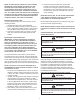
THERMOSTAT
2-STAGE HEATING WITH
2-STAGE COOLING
Two-Stage Thermostat
with Three Low Voltage Wires to
Remote
2
2
2
1
2
1
1
2
The following overcurrent protection devices are approved
for use.
• Time delay fuses
• HACR type circuit breakers
These devices have sucient time delay to permit the
motor-compressor to start and accelerate its load.
CAUTION
Three phase compressors are power phase dependent
and can rotate in either direction.
Verify proper rotation for three phase compressors by
ensuring the suction pressure drops and discharge
pressure rises when the compressor is energized.
To correct, disconnect power and switch any two leads at
the unit contactor and re-observe.
Route power supply and ground wires through the high
voltage port and terminate in accordance with the wiring
diagram provided inside the control panel cover.
Condensing unit control wiring requires 24 Volt minimum,
25VA service from the indoor transformer. Low voltage
wiring for two-stage units depends on the thermostat used
and the number of control wires between the indoor unit
and the condensing unit. Route control wires through the
low voltage port and terminate in accordance with the
wiring diagram provided inside the control panel cover.
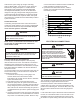
THERMOSTAT
SINGLE-STAGE HEATING
WITH
SINGLE-STAGE COOLING
CAUTION
When opening valves with retainers, open each valve
only until the top of the stem is 1/8” from the retainer. To
avoid loss of refrigerant, DO NOT apply pressure to the
retainer. When opening valves without a retainer remove
service valve cap and insert a hex wrench into the valve
stem and back out the stem by turning the hex wrench
counterclockwise. Open the valve until it contacts the rolled
lip of the valve body.
Adequate refrigerant charge for the matching HSVTC
evaporator coil and 15 feet of lineset is supplied with
the condensing unit. If using evaporator coils other than
HSVTC coil, it may be necessary to add or remove
refrigerant to attain proper charge. If line set exceeds 15
feet in length, refrigerant should be added at .6 ounces per
foot of liquid line.
Break vacuum by fully opening liquid service valve.
After the refrigerant charge has bled into the system,
open the suction service valve. The service valve cap is
the secondary seal for the valves and must be properly
tightened to prevent leaks. Make sure cap is clean and
apply refrigerant oil to threads and sealing surface on