
Installation Guide

10
Corrections must be in accordance with the latest edition of the
National Fuel Gas Code NFPA 54/ANSI Z223.1 and/or CAN/CSA B149
Installation Codes.
If resizing is required on any portion of the venting system, use the
appropriate table in the latest edition of the National Fuel Gas
Code ANSI Z223.1 and/or CAN/CSA B149 Installation Codes.
THERMOSTAT L OCATION
In an area having good air circulation, locate the thermostat about
five feet high on a vibration-free inside wall. Do not install the
thermostat where it may be influenced by any of the following:
• Drafts, or dead spots behind doors, in corners, or under
cabinets.
• Hot or cold air from registers.
• Radiant heat from the sun.
• Light fixtures or other appliances.
• Radiant heat from a fireplace.
• Concealed hot or cold water pipes, or chimneys.
• Unconditioned areas behind the thermostat, such as an
outside wall.
Consult the instructions packaged with the thermostat for mounting
instructions and further precautions.
C
OMBUSTION
AND
V
ENTILATION
A
IR
R
EQUIREMENTS
T
O
AVOID
PROPERTY
DAMAGE
,
PERSONAL
INJURY
OR
DEATH
,
SUFFICIENT
FRESH
AIR
FOR
PROPER
COMBUSTION
AND
VENTILATION
OF
FLUE
GASES
MUST
BE
SUPPLIED
. M
OST
HOMES
REQUIRE
OUTSIDE
AIR
BE
SUPPLIED
INTO
THE
FURNACE
AREA
.
WARNING
Improved construction and additional insulation in buildings have
reduced heat loss by reducing air infiltration and escape around
doors and windows. These changes have helped in reducing
heating/cooling costs but have created a problem supplying
combustion and ventilation air for gas fired and other fuel burning
appliances. Appliances that pull air out of the house (clothes
dryers, exhaust fans, fireplaces, etc.) increase the problem by
starving appliances for air.
House depressurization can cause back drafting or improper
combustion of gas-fired appliances, thereby exposing building
occupants to gas combustion products that could include carbon
monoxide.
If this furnace is to be installed in the same space with other gas
appliances, such as a water heater, ensure there is an adequate
supply of combustion and ventilation air for all appliances. Refer
to the latest edition of the National Fuel Gas Code NFPA 54/ANSI
Z223.1 or CAN/CSA B149 Installation Codes or applicable
provisions of the local building codes for determining the
combustion air requirements for the appliances.
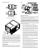
This furnace must use indoor air for combustion. It cannot be installed
as a direct vent (i.e., sealed combustion) furnace.
Most homes will require outside air be supplied to the furnace
area by means of ventilation grilles or ducts connecting directly
to the outdoors or spaces open to the outdoors such as attics or
crawl spaces.
C
ATEGORY
I V
ENTING
(V
ERTICAL
V
ENTING
)
T
O
PREVENT
POSSIBLE
PERSONAL
INJURY
OR
DEATH
DUE
TO
ASPHYXIATION
,
THIS
FURNACE
MUST
BE
C
ATEGORY
I
VENTED
. D
O
NOT
VENT
USING
C
ATEGORY
III
VENTING
.
WARNING
Category I Venting is venting at a non-positive pressure. A furnace
vented as Category I is considered a fan-assisted appliance and
the vent system does not have to be “gas tight.” NOTE: Single stage
gas furnaces with induced draft blowers draw products of
combustion through a heat exchanger allowing, in some instances,
common venting with natural draft appliances (i.e. water heaters).
All installations must be vented in accordance with National Fuel
Gas Code NFPA 54/ANSI Z223.1 - latest edition. In Canada, the
furnaces must be vented in accordance with the National Standard
of Canada, CAN/CSA B149.1 and CAN/CSA B149.2 - latest editions
and amendments.
NOTE: Masonry vent kit (MVK-01 and MVK-02) is to only be used
on interior masonry chimneys or qualifying exterior masonry
chimney applications identified in the MVK kit installation
instructions. To ensure safe and reliable operation, use only the
kit listed for your model.
Kit Input KBTU Range Limit Setting
MVK-01 40-100 250°F
MVK-02 120-140 290°F
Note :
This kit is for use on Amana
®
brand and Goodman
®
brand 80% AFUE,
33” tall “S” model furnaces installed in the upflow position only.
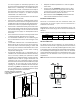
NOTE: The vertical height of the Category I venting system must be
at least as great as the horizontal length of the venting system.
T
O
PREVENT
POSSIBLE
PERSONAL
INJURY
OR
DEATH
DUE
TO
ASPHYXIATION
,
COMMON
VENTING
WITH
OTHER
MANUFACTURER
’
S
INDUCED
DRAFT
APPLIANCES
IS
NOT
ALLOWED
.
WARNING
The minimum vent diameter for the Category I venting system is as
shown:
UPFLOW COUNTERFLOW
40 4 Inch 4 Inch
60 4 Inch 4 Inch
80 4 Inch 4 Inch
100 5 Inch 5 Inch
120 5 Inch N/A
140 5 Inch N/A
MODEL
MINIMUM VENT