
Installation Guide
2
Gas Piping Connections .................................................. 15
Upflow Installations ....................................................... 16
Counterflow Installations .............................................. 16
Gas Piping Checks ........................................................... 17
Propane Gas Tanks and Piping ....................................... 17
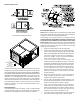
Ductwork ......................................................................... 17
Filters - Read This Section Before
Installing The Return Air Ductwork ................................ 18
Upright Installations ...................................................... 18
Horizontal Installations ................................................. 18
SEQUENCE OF OPERATION
(INTEGRATED IGNITION CONTROL) ..................................... 18
Power Up ......................................................................... 18
Heating Mode .................................................................. 18
Cooling Mode .................................................................. 19
Fan Only Mode ................................................................ 19
START-UP PROCEDURE AND ADJUSTMENT .............................. 19
Furnace Operation .......................................................... 19
Furnace Start-up ............................................................. 19
Furnace Shutdown .......................................................... 20
Gas Supply Pressure Measurement ................................ 20
Gas Manifold Pressure Measurement and Adjustment . 20
Gas Input Rate Measurement (Natural Gas Only) .......... 21
Temperature Rise............................................................. 21
Circulator Blower Speed Adjustment .............................. 22
OPERATIONAL CHECKS ............................................................ 22
Checking Duct Static ....................................................... 22
Burner Flame ................................................................... 22
SAFETY CIRCUIT DESCRIPTION ................................................ 23
General ............................................................................ 23
Integrated Control Module ............................................. 23
Primary Limit ................................................................... 23
Auxiliary Limit ................................................................. 23
Rollout Limits .................................................................. 23
Pressure Switches ........................................................... 23
Flame Sensor ................................................................... 23
TROUBLESHOOTING ............................................................... 23
Diagnostic Chart ............................................................. 23
Resetting From Lockout ................................................... 23
MAINTENANCE ........................................................................ 23
Annual inspection ........................................................... 24
Filters .............................................................................. 24
Filter Maintenance.......................................................... 24
Filter Removal ................................................................. 24
Induced Draft and Circulator Blower Motors ................ 24
Flame Sensor (Qualified Servicer Only) ......................... 24
Igniter (Qualified Servicer Only) .................................... 24
Burners ............................................................................ 24
CLEANING (QUALIFIED SERVICER ONLY) .................................. 24
BEFORE LEAVING AN INSTALLATION ........................................ 25
REPAIR AND REPLACEMENT PARTS .......................................... 25
COMPONENT ID ..................................................................... 26
TROUBLESHOOTING CHART .................................................... 27
BLOWER PERFORMANCE DATA ............................................... 30
*MES80 / CES80 ............................................................... 30
*MES80 / *CES80 Wiring Diagram........................................ 36