
Service Manual

142
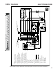
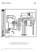
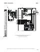
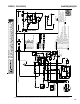
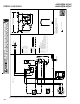
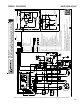
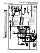
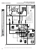
WIRING DIAGRAMS
HIGH VOLTAGE!
DISCONNECT ALL POWER BEFORE SERVICING OR INSTALLING THIS
UNIT. MULTIPLE POWER SOURCES MAY BE PRESENT. FAILURE TO
DO SO MAY CAUSE PROPERTY DAMAGE, PERSONAL INJURY OR DEATH.
Wiring is subject to change. Always refer to the wiring diagram on the unit for the most up-to-date wiring.
COM
XFMR-C
XFMR-R
SPEEDUP
C
NC
M1
K1
R
G
NO
K1
USE COPPER OR ALUMINUM WIRE
EQUIPMENT GROUND
35
2
14
TR
PC
PU
L1 L2
BL
W
BR
SR
PK
G
W
BR
BL
PU
R
BK
R
R
R
BK
BL
BL
R
208/240
24V
BL
R
M6
M5
RS2
W
BR
BL
BL
L1 L2
BK
BK
R
R
Y
Y
Y
M8
M7
BL
BL
BL
EBTDR
HTR2
FL HTR3
TL
FL HTR4 TL
8
9
7
6
5
4
3
1
2
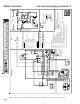
Typical Wiring Schematic MBR Blower with Electric Heat.
This wiring diagram is for reference only. Not all wiring is as shown above.
Refer to the appropriate wiring diagram for the unit being serviced.
USE COPPER WIRE
MBR