
Service Manual


SERVICING
94
(Note that the reading may be less than the actual printed
value of the capacitor).
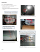
5. If you read a significantly lower capacitance or none at all,
then capacitor is dead and must be replaced.
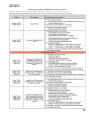
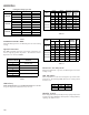
S-16ACHECKING FAN AND BLOWER MOTOR WINDINGS
(PSC MOTORS)
The auto reset fan motor overload is designed to protect the motor
against high temperature and high amperage conditions by
breaking the common circuit within the motor, similar to the
compressor internal overload. However, heat generated within
the motor is faster to dissipate than the compressor, allow at
least 45 minutes for the overload to reset, then retest.
WARNING
HIGH VOLTAGE!
Disconnect ALL power before servicing
or installing. Multiple power sources
may be present. Failure to do so may
cause property damage, personal injury
or death.
1. Remove the motor leads from its respective connection points
and capacitor (if applicable).
2. Check the continuity between each of the motor leads.
3. Touch one probe of the ohmmeter to the motor frame (ground)
and the other probe in turn to each lead.
If the windings do not test continuous or a reading is obtained
from lead to ground, replace the motor.
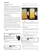
S-16BCHECKING FAN AND BLOWER MOTOR (ECM
MOTORS)
An ECM is an Electronically Commutated Motor which offers many
significant advantages over PSC motors. The ECM has near zero
rotor loss, synchronous machine operation, variable speed, low
noise, and programmable air flow. Because of the sophisticated
electronics within the ECM motor, some technicians are inti-
mated by the ECM motor; however, these fears are unfounded. GE
offers two ECM motor testers, and with a VOM meter, one can
easily perform basic troubleshooting on ECM motors. An ECM
motor requires power (line voltage) and a signal (24 volts) to
operate. The ECM motor stator contains permanent magnet. As a
result, the shaft feels "rough" when turned by hand. This is a
characteristic of the motor, not an indication of defective bear-
ings.
Line Voltage now present.
WARNING
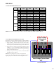
1. Disconnect the 5-pin connector from the motor.
2. Using a volt meter, check for line voltage at terminals #4 & #5
at the power connector. If no voltage is present:
3. Check the unit for incoming power See section S-1.
4. Check the control board, See section S-40.
5. If line voltage is present, reinsert the 5-pin connector and
remove the 16-pin connector.
6. Check for signal (24 volts) at the transformer.
7. Check for signal (24 volts) from the thermostat to the "G"
terminal at the 16-pin connector.
8. Using an ohmmeter, check for continuity from the #1 & #3
(common pins) to the transformer neutral or "C" thermostat
terminal. If you do not have continuity, the motor may
function erratically. Trace the common circuits, locate and
repair the open neutral.
9. Set the thermostat to "Fan-On". Using a voltmeter, check for
24 volts between pin # 15 (G) and common.
10. Disconnect power to compressor. Set thermostat to call for
cooling. Using a voltmeter, check for 24 volts at pin # 6 and/
or #14.
11. Set the thermostat to a call for heating. Using a voltmeter,
check for 24 volts at pin #2 and/or #11.
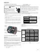
1
2
3
4
5
Lines 1 and 2 will be connected
for 12OVAC Power Connector
applications only
Gnd
AC Line Connection
AC Line Connection
}
11
19
2
3
4
5
6
7
816
15
14
13
12
10
OUT - OUT +
A
DJUST +/-
G (FAN)
Y1 Y/Y2
COOL
EM Ht/W2
DELAY
24 Vac (R)
COMMON2
HEAT
W/W1
BK/PWM (SPEED)
COMMON1 O (REV VALVE)
16-PIN ECM HARNESS CONNECTOR
If you do not read voltage and continuity as described, the
problem is in the control or interface board, but not the motor.
If you register voltage as described , the ECM power head is
defective and must be replaced.