
GSZC16 Installation


9
CT compatible
Air Handler/Furnace/Modular
Blower
CT compatible
Air Conditioner
Full CT system
benefits & features
CT compatible
Air Handler/Furnace/Modular
Blower
CT compatible
Heat Pump
Full CT system
benefits & features
C
OMFORT
N
ET
™ S
YSTEM
OVERVIEW
The ComfortNet system (or CT system) is a system that in-
cludes a ComfortNet compatible air handler/furnace/modular
blower and air conditioner or heat pump with a CTK0* thermo-
stat. Any other system configurations are considered invalid
ComfortNet systems and must be connected as a traditional
(or legacy) system. The following table compares the valid CT
systems.
A ComfortNet heating/air conditioning system differs from a legacy/traditional system in the manner in which the indoor unit,
outdoor unit and thermostat interact with one another. In a traditional system, the thermostat sends commands to the indoor
and outdoor units via analog 24 VAC signals. It is a one-way communication path in that the indoor and outdoor units typically
do not return information to the thermostat.
On the other hand, the indoor unit, outdoor unit, and thermostat comprising a ComfortNet system “communicate” digitally with
one another. It is now a two-way communications path. The thermostat still sends commands to the indoor and outdoor units.
However, the thermostat may also request and receive information from both the indoor and outdoor units. This information may
be displayed on the CT thermostat. The indoor and outdoor units also interact with one another. The outdoor unit may send
commands to or request information from the indoor unit.
Two-way digital communications is accomplished using only two wires. The thermostat and subsystem controls are powered
with 24 VAC. Thus, a maximum of 4 wires between the equipment and thermostat is all that is required to operate the system.
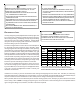
AIRFLOW C ONSIDERATION
Airflow demands are managed differently in a fully communi-
cating system than they are in a legacy wired system. The
system operating mode (as determined by the thermostat)
determines which unit calculates the system airflow demand.
If the indoor unit is responsible for determining the airflow de-
mand, it calculates the demand and sends it to the ECM motor.
If the outdoor unit or thermostat is responsible for determining
the demand, it calculates the demand and transmits the de-
mand along with a fan request to the indoor unit. The indoor
unit then sends the demand to the ECM motor. The table
below lists the various ComfortNet systems, the operating
mode, and airflow demand source.
For example, assume the system is a heat pump matched
with an air handler. With a call for low stage cooling, the heat
pump will calculate the system’s low stage cooling airflow
demand. The heat pump will then send a fan request along
with the low stage cooling airflow demand to the air handler.
Once received, the air handler will send the low stage cooling
airflow demand to the ECM motor. The ECM motor then deliv-
ers the low stage cooling airflow. The table at right lists the
nominal high and low stage airflow for the ComfortNet™ heat
pumps.
System
System
Operating Mode
Airflow Demand
Source
Cooling Heat Pump
Heat Pump Heating
Only
Heat Pump
HP + Electric Heat
Strips
> of Heat Pump or Air
Handler Demand
Electric Heat Strips
Only
Air Handler
Continuous Fan Thermostat
Cooling Heat Pump
Heat Pump Heating
Only
Heat Pump
Auxiliary Heating Furnace
Continuous Fan Thermostat
Heat Pump + Air
Handler
Heat Pump +
Furnace
High Low High Low
*SZC160241 800 600 800 600
*SZC160361 1200 800 1200 800
*SZC160481 1550 1100 1550 1100
*SZC160601 1800 1210 1800 1210
*SZC180361 1250 850 1250 850
*SZC180481 1750 1210 1750 1210
*SZC180601 1750 1210 1750 1210
Cooling Heating
Models