
Installation Manual


2
THIS UNIT IS EQUIPPED WITH A 24 VAC TRANSFORMER THAT POWERS
THE HEAT PUMP CONTROL BOARD. WHEN INSTALLED AS A
COMMUNICATING SYSTEM, ONLY 2 WIRES
ARE
NEEDED BETWEEN
INDOOR AND OUTDOOR EQUIPMENT. HOWEVER, WHEN INSTALLED AS
A NON-COMMUNICATING (LEGACY) SYSTEM, THE TRANSFORMER
WIRING (LOW VOLTAGE AND LINE VOLTAGE) MUST BE DISCONNECTED.
R
EFER TO THE LOW VOLTAGE WIRING SECTION FOR MORE DETAILS.
NOTICE
Should you have any questions please contact the local ofce
of the EPA.
If replacing a condensing unit or air handler, the system must
be manufacturer approved and Air Conditioning, Heating and
Refrigeration Institute (AHRI) matched. NOTE: Installation of
unmatched systems is strongly discouraged.
Outdoor units are approved for operation above 55°F in
cooling mode. Communicating units are equipped with two
speed of ECM fan motors and are not approved for use with
low ambient kits.
Damage to the unit caused by operating the unit in a structure
that is not complete (either as part of new construction or
renovation) is not covered by the warranty.
featureS
This heat pump is part of a ComfortBridge™ control system
designed to more efficiently control heat gain/loss with
better efciency and achieve targeted comfort conditions.
The system utilizes digital linkage between the indoor and
outdoor equipment and can be controlled by any single-stage
thermostat. The ComfortBridge™ control system reduces the
number of required thermostat wires, provides additional setup
features and enhanced active diagnostics through Bluetooth
connectivity with the downloadable CoolCloud™ app.
InStallatIon clearanceS
Special consideration must be given to location of the con-
densing unit(s) in regard to structures, obstructions, other
units, and any/all other factors that may interfere with air
circulation. Where possible, the top of the unit should be
completely unobstructed; however, if vertical conditions re-
quire placement beneath an obstruction there should be a
minimum of 60 inches between the top of the unit and the
obstruction(s). The specied dimensions meet requirements
for air circulation only. Consult all appropriate regulatory codes
prior to determining nal clearances.
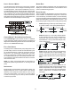
Another important consideration in selecting a location for the
unit(s) is the angle to obstructions. Either side adjacent the
valves can be placed toward the structure provided the side
away from the structure maintains minimum service clearance.
Corner installations are strongly discouraged.
OK!
OK!
AA AA
A
A
CC
C
C
OK!
OK!
OK!
OK!
NOT
RECO MMENDED
AA
AA
AA
AA
AA
B B B
B
Model Type
A
B
C
AA
Residential
10"
10"
18"
20"
Light Commercial
12" 12" 18"
24"
Minimum Airflow Clearance
This unit can be located at ground oor level or on at roofs. At
ground oor level, the unit must be on a solid, level foundation
that will not shift or settle. To reduce the possibility of sound
transmission, the foundation slab should not be in contact
with or be an integral part of the building foundation. Ensure
the foundation is sufcient to support the unit. A concrete slab
raised above ground level provides a suitable base.
rooftop InStallatIonS
If it is necessary to install this unit on a roof structure, ensure
the roof structure can support the weight and that proper
consideration is given to the weather-tight integrity of the roof.
Since the unit can vibrate during operation, sound vibration
transmission should be considered when installing the unit.
Vibration absorbing pads or springs can be installed between
the con-densing unit legs or frame and the roof mounting
assembly to reduce noise vibration.
NOTE: These units require special location consideration
in areas of heavy snow accumulation and/or areas with
prolonged continuous subfreezing temperatures. Heat pump
unit bases have cutouts under the outdoor coil that permit
drainage of frost accumulation. Situate the unit to permit
free unobstructed drainage of the defrost water and ice. A
minimum 3” clearance under the outdoor coil is required in
the milder climates.
In more severe weather locations, it is recommended that the
unit be elevated to allow unobstructed drainage and air ow.
The elevation minimums at right are recommended: