Service and Troubleshooting ANX, SSX, ASX, GSX, DSX, VSX Condensing Units, ANZ, SSZ, ASZ, GSZ, DSZ, VSZ Split System Heat Pumps GSXH5, ASXH5,GSZH5, ASZH5, With R-410A Refrigerant Blowers, Coils, & Accessories Pride and workmanship go into every product to provide our customers with quality products. It is possible, however, that during its lifetime a product may require service.
IMPORTANT INFORMATION CHECKING ECM MOTOR WINDINGS.........................81 ECM CFM ADJUSTMENTS MBE/AEPF ......................81 BLOWER PERFORMANCE DATA ...............................86 CHECKING HIGH EFFICIENCY MOTORS..................86 EEM BLOWER REPLACEMENT..................................87 MBR/AR*F ELECTRONIC BLOWER TIME DELAY RELAY...........................................................................88 CHECKING COMPRESSOR.........................................88 RESISTANCE TEST.............
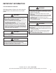
IMPORTANT INFORMATION SAFE REFRIGERANT HANDLING While these items will not cover every conceivable situation, they should serve as a useful guide. WARNING Refrigerants are heavier than air. They can “push out” the oxygen in your lungs or in any enclosed space. To avoid possible difficulty in breathing or death: • Never purge refrigerant into an enclosed room or space. By law, all refrigerant must be reclaimed. • If an indoor leak is suspected, thoroughly ventilate the area before beginning work.
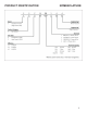
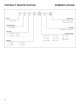
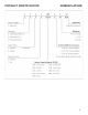
PRODUCT IDENTIFICATION NOMENCLATURE The model and manufacturing number are used for positive identification of component parts used in manufacturing. Please use these numbers when requesting service or parts information.
PRODUCT IDENTIFICATION NOMENCLATURE 5
PRODUCT IDENTIFICATION 6 NOMENCLATURE
PRODUCT IDENTIFICATION NOMENCLATURE G S X H 5 0 36 1 0 ** 1 2 3 4 5 6 7,8 9 10 11,12 Brand Engineering G - Goodman® Brand Major/Minor Revisions B - 1st Revision Product Category Varia�on S Split System R-410A Unit Type Electrical X Condenser 1 208/230 V, 1 Phase, 60 Hz Z Heat Pump Feature N Value H Enhanced B Classic C Premium Nominal Capacity 18 - 1.5 Ton 42 - 3.5 Tons 24 - 2.0 Tons 48 - 4.0 Tons 30 - 2.5 Tons 60 - 5.0 Tons 36 - 3.0 Tons SEER2 Sales Region 13.
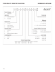
PRODUCT IDENTIFICATION NOMENCLATURE G S Z H 5 0 36 1 0 AA 1 2 3 4 5 6 7,8 9 10 11, 12 Brand G Engineering Major/Minor Revisions Goodman® Brand B - 1st Revision Product Category S Split System R-410A Unit Type - Split System X Condenser Z Heat Pump Electrical 1 208/230 V, 1 Phase, 60 Hz Feature N Value H Enhanced B Classic C Premium SEER2 Nominal Capacity 018 - 1½ tons 042 3½ Tons 024 - 2 tons 048 4 Tons 030 - 2½ tons 060 5 Tons 036 - 3 tons 13.4 - 13.7 = 3 16.
PRODUCT IDENTIFICATION NOMENCLATURE 9
PRODUCT IDENTIFICATION 10 NOMENCLATURE
PRODUCT IDENTIFICATION NOMENCLATURE 11
PRODUCT IDENTIFICATION NOMENCLATURE All Airhandlers use DIRECT DRIVE MOTORS. Power supply is AC 208-240v, 60 hz, 1 phase.
PRODUCT IDENTIFICATION A 1 PRODUCT M 2 S 3 T 4 NOMENCLATURE 36 5, 6 B 7 U 8 1 9 4 00 A 10 11, 12 13 A 14 MINOR REVISION A: Initial Release B: 1st Revision A: Corporate Air Handler MAJOR REVISION APPLICATION A: Initial Release B: 1st Revision C: Ceiling Mounted M: Multi-Positional W: Wall Mounted H: Horizontal Discharge Compatible Multi-Positional ELECTRIC HEAT KW REFRIGERANT 4 - R-410A 6 - R-410A or R-22 MOTOR ELECTRICAL S: MS-ECM V: VS-ECM Communicating 1 - 208/230 V, 1 Phase, 60 Hz CA
PRODUCT IDENTIFICATION G S X 11 1 2 3 090 1 4,5 6,7,8 AA 9 10,11 Brand Engineering G - Goodman brand Major/Minor Revisions A - Amana brand Type S Voltage 1 - 208/230V Single-Phase 60 Hz Split System 2 - 220/240V Single-Phase 50 Hz Type 3 - 208/230V Three-Phase 60 Hz X: Condenser R-410A 4 - 460V Three-Phase 60 Hz Z: Heat Pump R-410A 5 - 380/415V Three-Phase 50 Hz SEER 11 - 11 SEER 13 - 13 SEER Nominal Capacity 14 - 14 SEER 16 - 16 SEER 036 - 3 Tons 048 - 4 Tons 060 - 5 Tons 090 - 7
PRODUCT IDENTIFICATION GSX11 LIGHT COMMERCIAL GOODMAN® BRAND SPLIT X-R410A CONDENSERS 11 SEER Model/Rev Description GSX11090*AA GSX11120*AA Introduction of Goodman Light Commercial 11 SEER, R-410A Condensers. GSX111203AB GSX110903AB GSX111204AB GSX110904AB 208-230V and 460V 3 Phase condensing units with new ball valve/brackets, suction tube/assembly and panel w/offset.
PRODUCT IDENTIFICATION ASZ13 AMANA® BRAND SPLIT Z-R410A HEAT PUMP 13 SEER Model/Rev Description ASZ130**1AA Initial release of Amana® Brand 13 SEER Heat Pump R410A. ASZ130**1AB Introduces new revisions with improved circuiting for effective defrost. ASZ130[18, 36-60]1AB ASZ130[24-30]1AC Introduces models containing crankcase heater, CCH switch and upgraded defrost control.
PRODUCT IDENTIFICATION ASZ14 AMANA® BRAND SPLIT Z-R410A HEAT PUMP 14 SEER Model/Rev Description ASZ140**1AA Initial release of Amana® Brand 14 SEER Heat Pump R410A with sound blankets and Coresense control. ASZ140**1AB Screw locations moved in the top panel, base pans, louvers, and control box covers. ASZ140**1AC Horizontal style louvers. ASZ140[18, 42-48]1AD ASZ140[24-36, 60]1AE New steel muffler, and suction tubes w/shock loop.
PRODUCT IDENTIFICATION ASZ14 AMANA® BRAND SPLIT Z-R410A HEAT PUMP 14 SEER Model/Rev Description ASZ140381AA 35" chassis with 6-channel flowrator and ZP29K5 compressor. ASZ140[18-30]1BA Updated ratings and agency information. ASZ140[18-60]1KA Introduction of ready 15, 14 SEER heat pumps to meet the 2015 energy efficiency requirement. ASZ140[42,49]1KB Motor change on 3 & 3.5T 14 SEER & 2 & 2.5T 16 SEER. Increase blade gap. ASZ140181KC Change from copper wound motor to aluminum wound motor.
PRODUCT IDENTIFICATION ANZ13 AMANA® BRAND SPLIT SYSTEM N-BASE Z-R410A HEAT PUMP 13 SEER Model/Rev Description ANZ130[18-60]1AA Initial release of Amana® Brand Split System Base Heat Pump, 13 Seer R-410A units.
PRODUCT IDENTIFICATION DSZ16 DELUXE SPLIT Z-R410A HEAT PUMP 16 SEER Model/Rev Description DSZ160**1AA Initial release of Deluxe Goodman 2-stage 16 SEER heat pumps with R-410A. DSZ160241AC DSZ16036, 48, 60]1AB Sanhua (RANCO) reversing valves. DSZ18 DELUXE SPLIT Z-R410A HEAT PUMP 18 SEER Model/Rev Description DSZ180**1AA Initial release of Deluxe Goodman 2-stage 18 SEER heat pumps with R-410A. DSZ180[36, 48, 60]1AB Sanhua (RANCO) reversing valves.
PRODUCT IDENTIFICATION VSZ13 VALUE SPLIT Z-R410A HEAT PUMP 13 SEER Model/Rev Description VSZ13**1AA Initial release of Value Line 13 SEER heat pumps with R-410A. VSZ130[24 & 30]1AB Improved circuiting for effective defrost. VSZ130[24 & 36]1BA Initial release of models with 5mm Smart Coil™. VSZ130[18, 42, 48]1AB VSZ130241BB VSZ130301AC Models containing crankcase heater, CCH switch and upgraded defrost control.
PRODUCT IDENTIFICATION VSZ14 VALUE SPLIT Z-R410A HEAT PUMP 14 SEER Model/Rev Description VSZ14[018-060]1AA Introduction of ready 15, 14 SEER heat pumps to meet the 2015 efficiency requirement. VSZ140(18-30)1AB Energy guide update. PCBDM160 with new software. VSZ140421AB VSZ140491AB Motor change on 3 & 3.5T 14 SEER & 2 & 2.5T 16 SEER. Increase blade gap. VSZ140[18,30]1AC VSZ140[36,48,60]1AB Refrigerant charge reduction.
PRODUCT IDENTIFICATION GSZ13 GOODMAN SPLIT Z-R410A HEAT PUMP 13 SEER Model/Rev Description GSZ13**1AA Initial release with Regal Beloit motor. GSZ13**1AB GSZ13**3AA GSZ13**4AA Initial release with Broad Ocean motor. GSZ130[24 & 30]1AC Release of minor revision with improved circuiting for effective defrost. GSZ130[24 & 36]1BA Initial release of models with 5mm Smart Coil™. GSZ130241CA Release of 2 Ton models with a compressor change from ZP21K5EPFV130 to ZP20K5EPFV130.
PRODUCT IDENTIFICATION GSZ13 GOODMAN SPLIT Z-R410A HEAT PUMP 13 SEER Model/Rev Description GSZ130[19,31]1AD GSZ130241BE GSZ130251AC Create new Motor & Replace 0131M00294 with 0131M00800 GSZ130601AE Create new Motor 0131M00807 & Replace 0131M00061 with 0131M00807 GSZ130181AH GSZ130301AJ Replaced motor 0131M000266 with 0131M00811 GSZ130361BF GSZ130371AD GSZ130421AJ GSZ130481AH Replaced motor 0131M00018P with 0131M00813 GSZ130421AK GSZ130421AL Change from copper wound compressor motor to aluminum wo
PRODUCT IDENTIFICATION GSZ16 GOODMAN SPLIT Z-R410A HEAT PUMP 16 SEER Model/Rev Description GSZ160[18-48]1BA Initial release of Goodman 16 SEER, 13 EER Heat Pumps with 9.0+ HSPF GSZ1160601BA Initial release of Goodman 5 Ton 16 SEER, 13 EER Heat Pumps GSZ160241BB GSZ160301BB Motor change on 3 & 3.5T 14 SEER & 2 & 2.5T 16 SEER. Increase blade gap. GSZ160181BB 16 SEER 1.5T Heat Pumps, Remove Hard Start Kit GSZ160181BC Equivalent motor with Aluminum Windings replacing Copper Windings.
PRODUCT IDENTIFICATION SSZ14 SPECIAL HIGH FEATURE SPLIT Z-R410A HEAT PUMP 14 SEER Model/Rev Description SSZ140**1AA Initial release of Goodman 14 SEER Heat Pump R410A. SSZ140**1AB Screw locations moved in the top panel, base pans, louvers, and control box covers. SSZ140**1AC Broad Ocean Motors. SSZ140181AC SSZ140241AF SSZ140301AD Discharge line mufflers added. SSZ140361AF SSZ140[42-60]1AD Added discharge line mufflers. Replaced TXV and compensator with flowrator and accumulator.
PRODUCT IDENTIFICATION SSZ16 SPECIAL HIGH FEATURE SPLIT Z-R410A HEAT PUMP 16 SEER Model/Rev Description SSZ160**1AA Initial release of Goodman 16 SEER Heat Pump R410A. SSZ160**1AB Screw locations moved in the top panel, base pans, louvers, and control box covers. SSZ160**1AC Broad Ocean Motor. Updated muffler and standardized TXV. Compensator using ASZ18 SEER weldment to the SSZ160601AC. SSZ16[024-48]1AC SSZ160601AD Discharge line mufflers added.
PRODUCT IDENTIFICATION GSX13 GOODMAN BRAND SPLIT X-R410A CONDENSERS 13 SEER Model/Rev Description GSX130**1AA Initial release of Goodman 13 SEER R-410A Condensers with Regal Beloit motors GSX13061[1/3/4]AA Introduction of Goodman 13 SEER R-410A Condensers that supplement our current 5 ton models. GSX130363AB GSX130484AB GSX130603AB GSX130604AB Changed from the current four piece louver assembly, to a two piece louver plus a corner post on Goodman and value series 26" and 29" chassis.
PRODUCT IDENTIFICATION GSX13 GOODMAN BRAND SPLIT X-R410A CONDENSERS 13 SEER Mode l/ Re v De scripti on GSX130611AC Create new Motor 0131M00807 & Replace 0131M00061 with 0131M00807 GSX130241ED GSX130[30,60]1BG GSX130361EE GSX130[42,48]1BF Factory Refrigerant Charge Optimization GSX130181EH Changing Flat BOM structure to Indented BOM structure GSX130181EG Switching 3-legged and 4-legged compressors in 13SEER and 14SEER condensers to those with improved overload protection (OLP).
PRODUCT IDENTIFICATION GSX14 GOODMAN BRAND SPLIT X-R410A CONDENSERS 14 SEER Mode l/Re v De scription GSX14**1AA Int roduc tion of Goodman 14 SEE R R-410A models . GSX140[18-19]1KA GSX140[24-25]1KA GSX140[30-31]1KA GSX140[36-37]1KA GSX140[42, 48, 60]1KA Goodman Split X 14 Seer Condensing units. Introducing the Goodman 14 SEER standard condenser 5mm architecture with updated scroll compressors. GSX140241KB Replaced 1/12hp fan motor with 1/8hp fan motor. GSX140311AA Introduction of 12.
PRODUCT IDENTIFICATION GSX16 GOODMAN BRAND SPLIT X-R410A CONDENSERS 15 AND 16 SEER Model/Rev Description GSX160**1FA Initial release of the Goodman 16 SEER R410A Condensers. GSX160611FA New high capacity 5 ton model that will supplement the current GSX160601 models. GSX160[18-61]1FB Minor revision for GSX16s to include ball valves 0151R00045 and 0151R00046. GSX160601GA 7mm coils.
PRODUCT IDENTIFICATION SSX14 SPECIAL HIGH FEATURE SPLIT X-R410A CONDENSERS 14 SEER Model/Rev SSX140**1AA Description SSX14018, 241AC Initial release of Goodman 14 SEER AC 410A. Revisions have screw locations moved in the top panel, base pans, louvers, and control box covers. Revised condenser coils by removing [1] haripin.
PRODUCT IDENTIFICATION SSX16 SPECIAL HIGH FEATURE SPLIT X-R410A CONDENSER 16 SEER Model/Rev Description SSX160**1AA Introduces Goodman 16 SEER AC 410A SSX160**1AB New revisions have screw locations moved in the top panel, base pans, louvers, and control box covers. SSX160**1AB SSX160591AA New revisions have screw locations moved in the top panel, base pans, louvers, and control box covers. SSX160[24, 36, 48]1BA SSX160[30 & 42]1AA SmartCoil® coils.
PRODUCT IDENTIFICATION VSX13 VALUE SPLIT X-R410A CONDENSER 13 SEER Model/Rev Description VSX130[18-48]1AA Introduces Value Line 13 SEER condensing units with R-410A. VSX130611AA Supplements the 5 ton model GSX130611 to enhance performance. VSX130301AB Replaced fan motor to -294 and fan blade to -18 on the VSX130301AA. VSX130301AC VSX130[42-48]1AC Changed from current four piece louver assembly to a two piece louver assembly plus a corner post on Goodman and value series 26" and 29" chassis.
PRODUCT IDENTIFICATION VSX13 VALUE SPLIT X-R410A CONDENSER 13 SEER Mode l /Re v De scription VSX130611AC Create new Motor 0131M00807 & Replace 0131M00061 with 0131M00807 VSX13[241,361]EE VSX130301AG VSX130[421,481]AF VSX130601BE Factory Refrigerant Charge Optimization VSX130181EH Changing Flat BOM structure to Indented BOM structure VSX130181EG Switching 3-legged and 4-legged compressors in 13SEER and 14SEER condensers to those with improved overload protection (OLP).
PRODUCT IDENTIFICATION VSX14 VALUE SPLIT X-R410A CONDENSER 13 SEER Mode l /Re v De scription VSX140[18-19]1AA VSX140[24-25]1AA VSX140[30-31]1AA VSX140[36-37]1AA VSX140[42, 48, 60]1AA Introducing the 14 SEER standard condenser 5mm architecture with updated scroll compressors. VSX140241AB Replaced 1/12hp fan motor with 1/8hp fan motor.
PRODUCT IDENTIFICATION ANX13 AMANA® BRAND SPLIT SYSTEM N-BASE X-R410A CONDENSERS 13 SEER Description Model/Rev ANX130[18-24]1AA Launch of the Tier 1.5T & 2.0T models. Launched with 26" chasis to accommodate horizontal style louvers. ANX130[30-61]1AA Initial release. ANX130241BA Convert ANX13/14 1.5 and 2 ton models to Rechi compressors.
PRODUCT IDENTIFICATION ANX14 AMANA® BRAND SPLIT SYSTEM N-BASE X-R410A CONDENSERS 14 SEER Model/Rev Description ® ANX140[18-60]1AA Introducing the Amana Brand 14 SEER standard condenser 5mm architecture with updated scroll compressors. ANX140241AB Replaces 1/12hp fan motor with 1/8hp fan motor. ANX140431AA Introduction of ready 15, 12.2 EER air conditioning units.
PRODUCT IDENTIFICATION ASX13 AMANA® BRAND SPLIT X-CONDENSERS 13 SEER Model/Rev Description ASX130**1AA Initial release new models of Amana® Brand Deluxe 13 SEER AC R410A conditioners. ASX130611AA Initial release of new models of Amana® Brand Deluxe 13 SEER AC R410A conditioners; replaced ASX130601* models. ASX130611AA Introduction of Amana® brand 13 SEER R-410A Condensers that supplement our current 5 ton models. ASX130**1BA Initial release of models using SmartCoil® coils.
PRODUCT IDENTIFICATION ASX14 AMANA® BRAND SPLIT X-CONDENSERS 14 SEER Model/Rev Description ASX140**1AA Initial release of models of Amana® Brand Deluxe 14 SEER AC R410A conditioners. ASX140**1AB Screw locations moved in the top panel, base pans, louvers, and control box covers. ASX140**1AC Horizontal style louvers. ASX14018-361AD Revised condenser coils by removing (1) hairpin. R410A quantity reduced by 6 ounces.
PRODUCT IDENTIFICATION ASX14 AMANA® BRAND SPLIT X-CONDENSERS 14 SEER Model/Rev Description ASX140191KB Remove HS Kit from Control Panels of condenser units with updated ZP14K6E scroll compressors. ASX140241LA Change compressor from K6 to K5 on ASX140241 and DX14SA0241 ASX 140[30,43]1KB Change from copper wound motor to aluminum wound motor.
PRODUCT IDENTIFICATION ASX16 AMANA® BRAND SPLIT X-CONDENSERS 16 SEER Model/Rev Description ASX160**1AB Screw locations moved in the top panel, base pans, louvers, and control box covers. ASX160**1AC Horizontal style louvers. ASX160**1FA Single speed outdoor fan. ASX160611FA High capacity 5 ton models that supplement the current ASX160601 models. ASX160611GA 7mm coils. ASX160[24-60]1BA Wiring diagram updated with notes.
PRODUCT IDENTIFICATION ACNF A-SINGLE PIECE AIR HANDLER CEILING MOUNT N-UNCASED FLOWATER Model/Rev Description ACNF****1AA Release of all models of 13 SEER Dayton uncased air handlers. ACNF****16AA Release of all models of 13 SEER Dayton uncased air handlers suitable for use with R-22 & R-410A. ACNF****1AB Drain pan material change.
PRODUCT IDENTIFICATION AEPF A-SINGLE PIECE E-MULTI-POSITION VARIABLE SPEED PAINTED FLOWATER Model/Rev Description AEPF****16AA Introducation of new 13 SEER Air Handler Models suitable for use with R-22 and R-410A. AEPF****16BA Introduction of new models adding lower kW hit kits on the S&R plate. AEPF****16BB Replacement of the current spot welded blower housing with the same cinched or crimped design used on the 80% furnace line.
PRODUCT IDENTIFICATION ARUF A-SINGLE PIECE AIR HANDLER R-MULTI-POSITION PSC MOTOR UNPAINTED FLOWRATOR Model/Rev ARUF172916AA A24-00-2RCA Description Introduction of new Air Handler Models with all aluminum evaporator coils. Conversion includes coils, manifold, hairpin, flowrators, 3/8" return bend to 5/16" aluminum return bends.
PRODUCT IDENTIFICATION ARPT - R410A ONLY A-SINGLE PIECE AIR HANDLER R-MULTI-POSITION PSC MOTOR PAINTED FLOWRATER TXV Model/Rev Description ARPT***14AA Initial release of the new air handlers. ARPT***14AB Initial release of the air handlers manufactured at the Houston furnace facility. ARPT[18-36]B14AC ARPT[36-60]D14AC Serial plate changes.
PRODUCT IDENTIFICATION ASPT A-SINGLE PIECE AIR HANDLER S-MULTI-POSITION EEM MOTOR PAINTED TXV Model/Rev Description ASPT[24/36/48/60]*14 Introduction of new generation ASPT air handlers. ASPT36C 14AB ASPT[48/60]D14AB ASPT48D 14AC 9mm return bend coil changes to new generation of ASPT air handlers. ASPT24B 14AC ASPT30C 14AB ASPT36C 14AC Programmed Broad Ocean Motor. The supplier can program the motor instead of furnace plant, thus eliminating any programming installing issues.
PRODUCT IDENTIFICATION MBR MODULAR BLOWER AIR HANDLER R-MULTI-POSITION PSC MOTOR Model/Rev Description MBR****AA-1AA Initial release of a module blower with PSC blower motor. MBR****AA-1AB A quality improvement to use 0.75" Quiet Flex Insulation. MBR****AA-1AC Release of MBR/MBVC Models(Minor Revisions) for 11th St Plant.
PRODUCT IDENTIFICATION AWUF A SINGLE PIECE AIR HANDLER WALL MOUNT PSC MOTOR UNPAINTED FLOWRATOR Model/Rev Description AWUF****1AA Initial release of 13 SEER Dayton wall mount air handlers. AWUF****16AA Initial release 13 SEER Dayton wall mount air handlers suitable for use with R-22 and R410A refrigerant. AWUF3005-101AA Introduces 13 SEER Dayton wall mount air handlers using a Burr Oak Louvered Fin coil. AWUF****1BA Replaced wave fin design with new louvered fin design.
PRODUCT IDENTIFICATION AWUF A SINGLE PIECE AIR HANDLER WALL MOUNT PSC MOTOR UNPAINTED FLOWRATOR Model/Rev Description AWUF180[316,516,816]BC AWUF190[316,516,816]AB AWUF240[316,516,816]BC AWUF241016BC AWUF250[316,516,816]AB AWUF251016AB AWUF300[516,816]BD AWUF301016BD AWUF310[516,816]AC AWUF321016AC AWUF360[516,816]BD AWUF361016BD AWUF370[516,816]BC AWUF371016BC Release gasket and caps to seal leak. With this modification we will be able to meet 2% at 1 inch static leak and 1.4% leak rate at 0.
PRODUCT IDENTIFICATION CAPF C-INDOOR COIL A-UPFLOW/DOWNFLOW PAINTED FLOWRATOR Model/Rev Description CAPF*****6AA Initial release of CAPF Dayton Upflow/Downflow coils. CAPF*****6BA Burr Oak Louvered Fin released in place of the Wavy Fin. CAPF36***CA Redesigned for performance improvement from 2 row to 3 row. CAPF*****6DA Replaced existing copper coils and other associated parts with aluminum components. CAPF*****6DB Drain pan material changed.
PRODUCT IDENTIFICATION Model/Rev CAPFA1714A6AA CAPFA1714B6AA CAPFA1818C6BA CAPFA2318A6AA CAPFA2318B6AA CAPFA2318C6AA CAPFA2422A6AA CAPFA3022A6AA CAPFA2922A6AA CAPFA2922B6AA CAPFA2922C6AA CAPFA4226B6AA CAPFA4226C6AA CAPFA4226D6AA CAPFA1714A6BA CAPFA1714B6BA CAPFA1818A6CA CAPFA1818B6CA CAPFA1818C6CA CAPFA2318A6BA CAPFA2318B6BA CAPFA2318C6BA CAPFA2418A6BA CAPFA2418B6BA CAPFA2418C6BA CAPFA2422A6BA CAPFA2422B6BA CAPFA2422C6BA CAPFA2922A6BA CAPFA2922B6BA CAPFA2922C6BA CAPFA3022A6BA CAPFA3022B6BA CAPFA3022C6BA CAP
PRODUCT IDENTIFICATION CAPT C-INDOOR COIL A-UPFLOW/DOWNFLOW PAINTED CASED FLOWRATOR W/TXV Model/Rev Description CAPT3131B4BA CAPT3131C4BA Initial release of coils with factory-installed, non-adjustable TXV. Single stage AHRI ratings for CAPT3131 NTC combinations. CAPT3743C4AA CAPT3743D4AA Initial release of single stage AHRI ratings for CAPT3743 NTC combinations. CAPT4961C4AA CAPT4961D4AA Initial release of single stage AHRI ratings for CAPT4961C4 NTC combinations.
PRODUCT IDENTIFICATION CAUF/A C-INDOOR COIL A-UPFLOW/DOWNFLOW UNCASED FLOWRATOR Model/Rev CAUF*****6AA CAUF*****6BA CAUF****6*DA CAUF*****6DB CAUF1824(A/B/C)6RDB CAUF3636(A/B)6RDB CAUF3636(C/D)6RDB CAUF3642(C/D)6RDB CAUF3743(C/D)6RDB CAUF4860(C/D)6RDB CAUF4961(C/D)6RDB CAUF3137B6RAA CAUF36***CA CAUFA*****6AA CAUFA*****6BA CAUFA*****6BA CAUFA*****6CA Description Initial release of CAUF Dayton Upflow/Downflow coils. Burr Oak Louvered Fin released in place of the Wavy Fin.
PRODUCT IDENTIFICATION CSCF C-INDOOR COIL S-HORIZONTAL SLAB COIL UNPAINTED FLOWRATOR Model/Rev Description CSCF*****6AA Release 13 SEER CSCF slab horizontal coil. CSCF*****6BA Burr Oak Louvered Fin released in place of the Wavy Fin. The rows change by one, (i.e. 4 row to 3 row; 3 row to 2 row) where applicable. CSCF1824N6BB CSCF3036N6BB CSCF3642N6CB CSCF4860N6CB Drain pan material change. CSCF3642N6CA CSCF4860N6CA Release 13 SEER CSCF slab horizontal coil. Louvered fin project.
PRODUCT DESIGN This section gives a basic description of cooling unit operation, its various components and their basic operation. Ensure your system is properly sized for heat gain and loss according to methods of the Air Conditioning Contractors Association (ACCA) or equivalent. MBE blower cabinets are approved for applications with cooling coils of up to 0.8 inches W.C. external static pressure. The MBE models includes a feature that allows airflow to be changed by +10% or -15%.
PRODUCT DESIGN The ASX [16 & 18], ASZ [16 & 18], DSX[16 & 18] and DSZ [16 & 18] series split system units use a two-stage scroll compressor. The two-step modulator has an internal unloading mechanism that opens a bypass port in the first compression pocket, effectively reducing the displacement of the scroll. The opening and closing of the bypass port is controlled by an internal electrically operated solenoid.
PRODUCT DESIGN Molded Plug w/ Rectifier C Line Run Capacitor S R Line Internal Unloader Coil 24 Vac FIGURE B 1. It is expected that the majority of run hours will be in the low capacity, unloaded mode. 2. It allows a simple two-stage thermostat to control capacity through the second stage in both cooling and possibly heating if desired. Unloader Solenoid A nominal 24-volt direct current coil activates the internal unloader solenoid. The input control circuit voltage must be 18 to 28 volt ac.
SYSTEM OPERATION Cooling Cycle For legacy room thermostat: When the room thermostat calls for cool, the contacts of the room thermostat close making terminals R to Y1 & G (if thermostat calls for low stage cool), or R to Y1, Y2 & G (if thermostat calls for high stage cool), the low voltage circuit of the transformer is completed. Current now flows through the magnetic holding coils of the compressor contactor (CC) and fan relay (RFC).
SYSTEM OPERATION Heating Cycle The reversing valve on the GSZ, SSZ, ANZ, ASZ, DSZ GSZH5 and ASZH5 models is energized in the cooling cycle through the “O” terminal on the room thermostat. This draws in the normally open contact CC, starting the Reversing Valve compressor condenser fan motors. At the same time, contacts (Energized) RFC close, starting the indoor fan motor. These modelsCoil have a 24 volt reversing valve coil.
SYSTEM OPERATION Expansion Valve/Check Valve Assembly In Cooling Operation Expansion Valve/Check Valve Assembly In Heating Operation Most expansion valves used in current Amana Heat Pump products use an internally checked expansion valve. This type of expansion valve does not require an external check valve as shown above.
SYSTEM OPERATION NOTE: If more than two heater elements are on the heater assembly, it will contain a second heat sequencer, HR2,which will control the 3rd and 4th heater elements if available. If the first stage heat demand, “W1” cannot be satisfied by the heat pump, the temperature indoors will continue to drop. The room thermostat will then energize “W2” and 24Vac will be supplied to HR2 on the heater assembly. When the “W2” demand is satisfied, the room thermostat will remove the 24Vac from HR2.
SYSTEM OPERATION As long as the thermostat is set for heating, the reversing valve will be in the de-energized position for heating except during a defrost cycle. 5.1 The heat pump will be on and operating in the heating mode as described the Heating Operation in section 4. 5.
SYSTEM OPERATION NOTE: If more than two heater elements are on the heater assembly, it will contain a second heat sequencer, HR2, which will control the 3rd and 4th heater elements if available. For the 3rd and 4th heater elements to operate on a second stage heat demand, the PJ4 jumper on the VSTB inside the MBE/ AEPF must be cut. With the PJ4 jumper cut, the VSTB will run the blower motor on low speed on a “W1” only demand.
SYSTEM OPERATION NOTE: If more than two heater elements are on the heater assembly, it will contain a second heat sequencer, HR2, which will control the 3rd and 4th heater elements if available. For the 3rd and 4th heater elements to operate on a third stage heat demand, the PJ4 jumper on the VSTB inside the MBE/AEPF must be cut. If the second stage heat demand, “W2”, cannot be satisfied by the heat pump, the temperature indoors will continue to drop.
SYSTEM OPERATION 1.1 On a demand for cooling, the room thermostat energizes “G” and “Y1” and 24Vac is supplied to “G” and “Ylow/Y1” of the MBE/AEPF unit. The VSTB inside the MBE/AEPF will turn on the blower motor and the motor will ramp up to 60% of the speed programmed in the motor based on the settings for dip switch 5 and 6. The VSTB will supply 24Vac to “Ylow/Y1” at the condenser and the compressor and condenser fan starts in low speed operation. 1.
SYSTEM OPERATION 3.1 On a demand for cooling, the room thermostat energizes “G” and “Y1” and 24Vac is supplied to “G” and “Ylow/Y1” of the MBE unit. The VSTB inside the MBE will turn on the blower motor and the motor will ramp up to 60% of the speed programmed in the motor based on the settings for dip switch 5 and 6. The VSTB will supply 24Vac to “Y” at the heat pump and the compressor and outdoor fan starts in low speed operation. 3.
SYSTEM OPERATION 4.5 As the temperature indoors increase, it will reach a point where the “W2/W3” demand is satisfied. When this happens, the room thermostat will remove the 24Vac from “E/W1” of the MBE/AEPF. The contacts on HR1 will open between 30 to 70 seconds and turn off the 1st and 2nd heater elements. If the “Y2” demand is present and becomes satisfied the room thermostat will remove the 24Vac from “Y/Y2” of the MBE and the blower motor will change to 60% of the programmed cfm.
SERVICING Checking Voltage 1. Remove outer case, control panel cover, etc., from unit being tested. With power ON: WARNING Line voltage now present. 2. Using a voltmeter, measure the voltage across terminals L1 and L2 of the contactor for the condensing unit or at the field connections for the air handler or heaters. 3. No reading - indicates open wiring, open fuse(s) no power or etc., from unit to fused disconnect service. Repair as needed. 4.
SERVICING Resistance Heaters 1. Set room thermostat to a higher setting than room temperature so both stages call for heat. 2. With voltmeter, check for 24 volts at each heater relay. 3. No voltage indicates the trouble is in the thermostat or wiring. 4. Check the continuity of the thermostat and wiring. Repair or replace as necessary. NOTE: Consideration must be given to how the heaters are wired (O.D.T. and etc.). Also safety devices must be checked for continuity.
SERVICING 1. Disconnect wire leads from terminals 2 and 4 of Fan Relay Cooling and 2 and 4, 5 and 6 of Fan Relay Heating. 2. Using an ohmmeter, test between 2 and 4 - should read open. Test between 5 and 6 - should read continuous. 3. With power ON, energize the relays. WARNING Line voltage now present. Testing Compressor Contactor (Single Phase) Three Phase Using a voltmeter, test across terminals: 1. L1-L2, L1-L3, and L2-L3 - If voltage is present, proceed to B.
SERVICING WARNING Line voltage now present. 4. The measured voltage between circuit 3 and circuits 2 or 1 should be approximately 0VAC, which indicates the relay contacts are closed. A voltage measurement of approximately 115VAC indicates the relay is open. Replace the control if the relay checks open when it should be closed. See notes and cautions below.
SERVICING 1. Apply power to unit and set thermostat to cool and set for a call for cool. 2. Low pressure switch should open at 21 PSIG, and auto reset (close) at approximately 50 PSIG. 3. If low pressure switch does not operate in these parameters replace switch. Test 2. Testing Low Pressure Control in Heating Mode 1. Connect refrigerant gages to unit. 2. Disconnect power to outdoor unit. 3. Remove control panel cover. 4.
SERVICING Once attached, CoreSense™ provides around-the-clock monitoring for common electrical problems, compressor defects and broad system faults. If a glitch is detected, an LED indicator flashes the proper alert codes to help you quickly pinpoint the problem. See Diagnostic Table: 3-Wire CoreSense™ Module on following pages.
SERVICING Status LED Green “POWER” Red “TRIP” Diagnostics Table: 2-Wire Comfort Alert™ Module Status LED Description Module has power Status LED Troubleshooting Information Supply voltage is present at module terminals Thermostat demand signal 1. Compressor protector is open Y1 is present, but the 2. Outdoor unit power disconnect is open compressor is not 3. Compressor circuit breaker or fuse(s) is open running 4. Broken wire or connector is not making contact 5.
SERVICING Diagnostics Table: Coresense™ Module Flash code number corresponds to the number of LED flashes, followed by a pause and then repeated. TRIP and ALERT LEDs flashing at the same time mean control circuit voltage is too low for operation.
SERVICING Diagnostics Table: Coresense™ Module Flash code number corresponds to the number of LED flashes, followed by a pause and then repeated. TRIP and ALERT LEDs flashing at the same time mean control circuit voltage is too low for operation. Status Description Yellow "ALERT" Flash Code 4 Locked Rotor Yellow "ALERT" Flash Code 5 Compressor (Moderate Run) Trip Red "LOCK" Flash Code 2 Yellow Off Troubleshooting Information 1. Run capacitor has failed 2.
SERVICING Table 1 - Quick Reference Table Alert Code Alert Condition Lock Level Normal Run Normal operation, no trip N/A Solid Yellow Long run time. Compressor is on running for more than 18 Code1 N/A Yellow Flash 1 hours. (Code1 is disabled in Heat Pump mode.) Compressor (pressure) trip. Compressor runs for 12 sec Code2 to 15 min followed by a compressor trip condition lasting 4x consecutive Yellow Flash 2 longer than 7 min. Pressure switch cycling.
SERVICING Checking Capacitor Capacitor, Run A run capacitor is wired across the auxiliary and main windings of a single phase permanent split capacitor motor. The capacitors primary function is to reduce the line current while greatly improving the torque characteristics of a motor. This is accomplished by using the 90° phase relationship between the capacitor current and voltage in conjunction with the motor windings, so that the motor will give two phase operation when connected to a single phase circuit.
SERVICING To prevent the compressor from short cycling, a Time Delay Relay (Cycle Protector) has been added to the low voltage circuit. Testing a Run Capacitor Under Load 1. Measure the amperage of the wire from Herm on the capacitor to start terminal on compressor. 2. Multiply the amperage reading by the constant of 2,652 3. Measure voltage across the capacitor between “HERM” and “C” terminals this is the measured voltage across the start and run terminals on the compressor. 4.
SERVICING } 1 2 Lines 1 and 2 will be connected for 12OVAC Power Connector applications only 3 Gnd 4 AC Line Connection 5 AC Line Connection OUT - 8 16 OUT + ADJUST +/- 7 15 G (FAN) Y1 6 14 Y/Y2 COOL 5 13 EM Ht/W2 DELAY 4 12 24 Vac (R) COMMON2 3 11 HEAT W/W1 2 10 BK/PWM (SPEED) COMMON1 1 9 O (REV VALVE) 16-PIN ECM HARNESS CONNECTOR If you do not read voltage and continuity as described, the problem is in the control or interface board, but not the motor.
SERVICING Dipswitch Functions The MBE / AEPF air handler motors have an electronic control that contains an eight (8) position dip switch. The function of these dipswitches are shown in Table 1. Function 1 2 3 4 5 6 7 MBE1600 El ectri c Hea t N/A Indoor Thermos ta t Cool i ng & Hea t Pump CFM Table 1 CFM Delivery Tables 2, 3, 5 and 6 show the CFM output for dipswitch combinations 1-2, and 5-6.
SERVICING CFM Delivery Tables 10-Electric Heat and 11-Cooling/Heat Pump show the CFM output for dipswitch combinations 1-2, and 5-6.
- Check line voltage for variation or "sag". - Check low voltage connections (G, Y, W, R, C) at motor, unseated pins in motor harness connectors. - Check-out system controls - Thermostat. - Perform Moisture Check.* - Does removing panel or filter reduce "puffing"? - Check/replace filter. - Check/correct duct restrictions. - Adjust to correct blow er speed setting. - Incorrect or dirty filter(s). - Incorrect supply or return ductw ork. - Incorrect blow er speed setting.
- Check/replace filter. - Check/correct duct restrictions. - Adjust to correct blow er speed setting. - Current leakage from controls into G, Y, or W. - - Blow er w on't shut off. - Air noise. - Motor failure or malfunction has occurred and moisture is present. - Replace motor and perform Moisture Check.* - Moisture in motor/control module. - "Hunts" or "puffs" at high CFM (speed). - Turn pow er OFF prior to repair. Wait 5 minutes after disconnecting pow er before opening motor.
SERVICING Blower Performance Data SPEED HIGH MEDIUM LOW STATIC MBR800**-* SCFM MBR1200**-* SCFM MBR1600**-* SCFM MBR2000**-* SCFM 0.1 1,240 1,500 1,800 2,160 0.2 1,170 1,460 1,740 2,080 0.3 1,120 1,360 1,680 1,990 0.4 1,060 1,280 1,610 1,890 0.5 980 1,200 1,520 1,790 0.6 900 1,110 1,430 1,690 1,730 0.1 900 1,380 1,540 0.2 850 1,320 1,490 1,670 0.3 790 1,270 1,450 1,590 0.4 740 1,200 1,400 1,520 0.5 680 1,140 13,560 1,420 0.
SERVICING EEM Blower Replacement For AWUF19-25, AWUF31-32, and AWUF37 Air Handlers. 1. Disconnect power at main electrical panel. 2. Remove front access panel. 3. Remove the two screws on each side holding the lower control box and move out of the way to give access to the blower assembly 5. Install cardboard or rug over coil to protect fins from damage. 6. Remove the three 3/8” screws holding the blower in place. 4.
SERVICING During an electric heat only demand, “W1” is energized but “G” is not. The blower motor is connected to the normally closed contacts of the relay on the EBTDR board. The other side of this set of contacts is connected to the heat sequencer on the heater assembly that provides power to the first heater element.
SERVICING Ignition cannot occur at the venting terminal without the presence of contaminant air, and cannot occur externally from the venting terminal without the presence of an external ignition source. Therefore, proper evacuation of a hermetic system is essential at the time of manufacture and during servicing. To reduce the possibility of external ignition, all open flame, electrical power, and other heat sources should be extinguished or turned off prior to servicing a system.
SERVICING 6. If ground is indicated, replace the compressor. The resistance reading should be infinity. If there is any reading on meter, there is some continuity to ground and compressor should be considered defective. Compressor Ground Test WARNING Damage can occur to the glass embedded terminals if the leads are not properly removed. This can result in terminal and hot oil discharging.
SERVICING A crankcase heater will not prevent compressor damage due to a floodback or over charge condition. WARNING Line voltage now present. • If the compressor starts and continues to run, the cause for failure is somewhere else in the system. • If the compressor fails to start - replace.
SERVICING Trouble Shooting Mechanical Failures on a Reversing Valve by Temperature 1. When operating properly the valve contains refrigerant gases at certain temperatures. 2. The discharge line should be the same temperature after the valves discharge line. 3. The true suction should be the same as the suction line after the valve.
SERVICING WARNING Disconnect ALL power before servicing. 7. Remove the wiring from the control terminals. 8. Using an ohmmeter test for continuity across the normally closed contacts. No reading indicates the control is open - replace if necessary. Make sure the limits are cool before testing. If Found Open - Replace - Do Not Wire Around. Checking Heater Elements Optional electric heaters may be added, in the quantities shown in the spec sheet for each model unit, to provide electric resistance heating.
SERVICING ELECTRIC HEATER CAPACITY BTUH HTR KW 3.0 KW 4.7 KW 6.0 KW 7.0 KW 9.5 KW 14.2 KW 19.5 KW 21.0 KW BTUH 10200 16200 20400 23800 32400 48600 66500 71600 FORMULAS: Heating Output = KW x 3413 x Corr. Factor Actual CFM = CFM (from table) x Corr. Factor BTUH = KW x 3413 NOTE: The link is designed to open at approximately 333°F. DO NOT WIRE AROUND - determine reason for failure. Checking Heater Elements WARNING BTUH = CFM x 1.08 x Temperature Rise (T) CFM = KW x 3413 1.08 x T T = BTUH CFM x 1.
SERVICING 5. When brazing, sweep the tubing with dry nitrogen to prevent the formation of oxides on the inside surfaces. 6. Complete any repair by replacing the liquid line drier in the system, evacuate and charge. Brazing Materials IMPORTANT NOTE: Torch heat required to braze tubes of various sizes is proportional to the size of the tube. Tubes of smaller size require less heat to bring the tube to brazing temperature before adding brazing alloy. Applying too much heat to any tube can melt the tube.
SERVICING condensable air and moisture. As an alternative, the Triple Evacuation Method is detailed in the Service Manual for this product model. It is recommended to remove the Schrader Cores from the service valves using a core-removal tool to expedite the evacuation procedure. 1. Connect the vacuum pump, micron gauge, and vacuum rated hoses to both service valves. Evacuation must use both service valves to eliminate system mechanical seals. 2.
SERVICING NOTE: R410A should be drawn out of the storage container or drum in liquid form due to its fractionation properties, but should be “Flashed” to its gas state before entering the system. There is commercially available restriction devices that fit into the system charging hose set to accomplish this. DO NOT charge liquid R410A into the compressor. NOTE: Power must be supplied to the 18 SEER outdoor units containing ECM motors before the power is applied to the indoor unit.
SERVICING for best possible readings. Use liquid line temperature to determine subcooling and vapor temperature to determine superheat. 3. Check subcooling and superheat. Systems with TXV application should have a subcooling of 5 to 7°F and superheat of 7 to 9°F. NOTE: To adjust superheat, turn the valve stem clockwise to increase and counter clockwise to decrease. 4. If subcooling and superheat are low, adjust TXV to 7 to 9ºF superheat, and then check subcooling. 5.
SERVICING Pistons Used in Outdoor Heat Pump Coils Goodman 14 SEER Heat Pumps Model Cur. Rev Piston Prev. Rev Piston G/VSZ140181 LA .032 KF .039 G/VSZ140241 LA .047 KH .047 G/VSZ140301 KG .052 KF .052 G/VSZ140361 KE .059 LA .059 G/VSZ140421 KE .061 KD .061 G/VSZ140481 KF .065 KE .065 G/VSZ140491 KE .065 KD .065 G/VSZ140601 KE .065 KD .065 Amana 14 SEER Heat Pumps Model Cur. Rev Piston Prev. Rev Piston ASZ140181 KE .039 KD .039 ASZ140241 KD .047 KC .047 ASZ140301 KD .052 KC .052 ASZ140361 KD .059 KC .
SERVICING 5. Capture the charge, replace the valve and drier, evacuate and recharge. Checking Restricted Liquid Line When the system is operating, the liquid line is warm to the touch. If the liquid line is restricted, a definite temperature drop will be noticed at the point of restriction. In severe cases, frost will form at the restriction and extend down the line in the direction of the flow. Discharge and suction pressures will be low, giving the appearance of an undercharged unit.
SERVICING Pressure vs. Temperature Chart R-410A PSIG 12 14 16 18 20 22 24 26 28 30 32 34 36 38 40 42 44 46 48 50 52 54 56 58 60 62 64 66 68 70 72 74 76 78 80 82 84 86 88 90 92 94 96 98 100 102 104 106 108 110 112 °F -37.7 -34.7 -32.0 -29.4 -36.9 -24.5 -22.2 -20.0 -17.9 -15.8 -13.8 -11.9 -10.1 -8.3 -6.5 -4.5 -3.2 -1.6 0.0 1.5 3.0 4.5 5.9 7.3 8.6 10.0 11.3 12.6 13.8 15.1 16.3 17.5 18.7 19.8 21.0 22.1 23.2 24.3 25.4 26.4 27.4 28.5 29.5 30.5 31.2 32.2 33.2 34.1 35.1 35.5 36.9 PSIG 114.0 116.0 118.0 120.0 122.
SERVICING REQUIRED LIQUID LINE TEMPERATURE LIQUID PRESSURE AT SERVICE VALVE (PSIG) 189 195 202 208 215 222 229 236 243 251 259 266 274 283 291 299 308 317 326 335 345 354 364 374 384 395 406 416 427 439 450 462 474 486 499 511 102 8 58 60 62 64 66 68 70 72 74 76 78 80 82 84 86 88 90 92 94 96 98 100 102 104 106 108 110 112 114 116 118 120 122 124 126 128 REQUIRED SUBCOOLING TEMPERATURE (°F) 10 12 14 16 56 54 52 50 52 54 56 58 60 58 56 54 62 60 58 56 64 62 60 58 66 64 62 60 68 66 64 62 70 68 66 64 72 70
SERVICING Suction Line Drier Clean-Up Method The POE oils used with R410A refrigerant is an excellent solvent. In the case of a burnout, the POE oils will remove any burnout residue left in the system. If not captured by the refrigerant filter, they will collect in the compressor or other system components, causing a failure of the replacement compressor and/or spread contaminants throughout the system, damaging additional components.
SERVICING Two Piece Air Handler External Static Pressure To determine proper airflow, proceed as follows: 1. Using a Inclined Manometer or Magnehelic gauge, measure the static pressure between the outlet of the evaporator coil and the inlet of the air handler, this will be a negative pressure (For Example: .30” wc). 2. Measure the static pressure of the supply duct at the outlet of the unit, this should be a positive pressure (For Example: .20” wc). 3. Add the two readings together (For Example: .30” wc + .
SERVICING Cleaning Aluminum Coils Evaporator coils and air handlers are equipped with an aluminum tube evaporator coil. The safest way to clean the evaporator coil is to simply flush the coil with water. This cleaning practice remains as the recommended cleaning method for both copper tube and aluminum tube residential cooling coils. An alternate cleaning method is to use one of the products listed in the technical publication TP-109 (shipped in the literature bag with the unit) to clean the coils.
WIRING DIAGRAMS 10kw and Below, One Stage Electric Heat ED IT E H R C W G R BL U EE E N From Air Handler G W2 R C G WHITE W2 1 4 1 BROWN THERMOSTAT EMERGENCY HEAT RELAY E R OT/EHR18-60 O Y C R W2 O Y YE R O G E IT E W O LL H ED AN W R U BL E From Outdoor Unit 15kw and Above, Two Stage Electric Heat From Air Handler SEE NOTE W ED O R W2 BR H IT E N G G W N EE R E BL U C W3 R C G WHITE W2 1 4 1 BROWN BLACK RED EMERGENCY HEAT RELAY THERMOSTAT E
WIRING DIAGRAMS 15kw and Above with Two OT/EHR18-60's, Two Stage Electric Heat and Two Stage Thermostat From Air Handler G W2 RE D BR O W IT E W H C G RE EN BL UE N OT/EHR18-60 #1 W3 R 2 G BROWN W2 1 2 3 1 4 WHITE BLACK RED EMERGENCY HEAT RELAY W3 THERMOSTAT E OT/EHR18-60 #2 O Y 2 2 3 BLUE WHITE 1 4 1 BROWN BLACK RED EMERGENCY HEAT RELAY THERMOSTAT O Y H W NG RA O W O LL YE E W2 E IT R D RE C UE BL HIGH VOLTAGE! DISCONNECT ALL POWER BEFORE SERVICING OR INSTALLI
WIRING DIAGRAMS HIGH VOLTAGE! DISCONNECT ALL POWER BEFORE SERVICING OR INSTALLING THIS UNIT. MULTIPLE POWER SOURCES MAY BE PRESENT. FAILURE TO DO SO MAY CAUSE PROPERTY DAMAGE, PERSONAL INJURY OR DEATH. 3-Phase Heat Kit 25kW Heat Kit Wiring is subject to change. Always refer to the wiring diagram on the unit for the most up-to-date wiring. 108 Wiring is subject to change. Always refer to the wiring diagram on the unit for the most up-to-date wiring.
WIRING DIAGRAMS SEE N OTE S 2 & 6 BL RD GR ADPF, ARPF, ARUF, ATUF L1 L2 BK RD PLM 1 2 3 4 5 6 7 8 9 PLF 1 2 3 4 5 6 7 8 9 TERMINA L BLOC K SHOW N FOR 50HZ MODELS ONLY WH BR SR EQ UIPMENT GROUND USE COPPE R W IRE GRND 208/240 VOLTS BK PU RD BR BL WH SEE NOT E 4 L1 BR PLM 2 1 PLM WH HIGH VOLTAGE! DISCONNECT ALL POWER BEFORE SERVICING OR INSTALLING THIS UNIT. MULTIPLE POWER SOURCES MAY BE PRESENT. FAILURE TO DO SO MAY CAUSE PROPERTY DAMAGE, PERSONAL INJURY OR DEATH.
WIRING DIAGRAMS AEPF FL FL FL HTR1 TL FL HTR2 TL FL BK BK 4 M1 W BK BK M1 R BK 8 R PU R BL 4 BR 5 M2 R2 BK BK BL 3 M1 M4 R M1 Y R W 6 M4 M5 M7 M6 M8 3 R R2 BK R BL 4 BR 5 W 6 7 7 BK 7 Y 8 R 8 Y BK 9 R 9 BL BK 8 9 L2 L1 ONE (1) ELEMENT ROWS L2 L1 TWO (2) ELEMENT ROWS L2 L1 L2 THREE (3) ELEMENT ROWS L1 L2 L1 L2 FOUR (4) ELEMENT ROWS AFTER INSTALLING OPTIONAL HEAT KIT, MARK AN "X" IN THE PROVIDED ABOVE.
WIRING DIAGRAMS AEPF******CA FL FL HTR1 TL PL1 BK BK FL HTR2 TL BK RD 2 BK BK WH PU RD M1 R 6 BK 3 HTR3 TL M2 BK RD BK 8 RD RD FL BK 6 1 R2 BL 4 BK 1 BR 5 RD 2 BK RD M1 YL M4 M5 M7 M6 M8 R1 6 3 BL M3 M2 RD R2 BK BK BL 4 BR 5 WH RD 6 7 RD 7 YL 8 YL BK 8 RD 9 BL BK 8 RD 9 9 L2 L1 ONE(1)ELEMENTROWS L2 L1 L2 TWO(2)ELEMENTROWS L1 L2 THREE(3)ELEMENTROWS L1 L2 L1 L2 FOUR(4)ELEMENTROWS AFTERINSTALLINGOPTIONALHEATKIT, MARKA"X"INTH
HIGH VOLTAGE! DISCONNECT ALL POWER BEFORE SERVICING OR INSTALLING THIS UNIT. MULTIPLE POWER SOURCES MAY BE PRESENT. FAILURE TO DO SO MAY CAUSE PROPERTY DAMAGE, PERSONAL INJURY OR DEATH. WIRING DIAGRAMS 112 AR[090-120]4 Wiring is subject to change. Always refer to the wiring diagram on the unit for the most up-to-date wiring.
1) RED WIRES TO BE ON TRANSFORMER TERMINAL "3" FOR 240 VOLTS AND ON TERMINAL "2" FOR 208 VOLTS. 2) SEE COMPOSITE WIRING DIAGRAMS IN INSTALLATION INSTRUCTIONS FOR PROPER LOW VOLTAGE WIRING CONNECTIONS. 3) CONFIRM SPEED TAP SELECTED IS APPROPRIATE FOR APPLICATION. IF SPEED TAP NEEDS TO BE CHANGED, CONNECT APPROPRIATE MOTOR WIRE (RED FOR LOW, BLUE FOR MEDIUM, AND BLACK FOR HIGH SPEED) ON "COM" CONNECTION OF THE EBTDR. INACTIVE MOTOR WIRES MUST BE CONNECTED TO "M1 OR M2" ON EBTDR.
USE MIN. 75°C FIELD WIRE (SEE RATING PLATE) COPPER POWER SUPPLY L2 BK R BK M2 M1 BK PU WH BL ONE (1) ELEMENT ROWS RD TL RD BK PL L1 RD BK L2 BK R BK RD M2 M1 HTR1 HTR2 M4 M3 BL WH BK PU RD TWO (2) ELEMENT ROWS RD TL TL BL WH GR W1 W2 Wiring is subject to change. Always refer to the wiring diagram on the unit for the most up-to-date wiring.
L2 BK R RD TL PU WH BL BK BK RD ONE (1) ELEMENT ROWS BK M2 M1 HTR 1 9 8 7 6 5 4 3 2 1 RD L1 BK FL L2 FL M2 M1 RD M4 M3 TL TL WH PU BL RD BK RD BK TW O (2) ELEMENT ROW S BK RD BK R HTR2 HTR1 9 8 7 6 5 4 3 2 1 L1 L2 BK RD BK RD YL R1 M4 M3 BK M2 R2 BL TL YL M1 BK RD TL TL WH PU BR RD BL BK THREE (3) ELEMENT ROW S L2 RD M2 RD HTR3 HTR2 HTR1 M1 BK L1 YL FL FL FL 9 8 7 6 5 4 3 2 1 L1 BK RD L2 L1 YL BL
WH RD or BK B A BL 1 4 7 WH COPPER POWER SUPPLY (USE RATING PLATE) USE MIN. 75° C FIELD WIRE GR CR PU IF REPLACEMENT OF THE ORIGINAL WIRES SUPPLIED WITH THIS ASSEMBLY IS NECESSARY, USE WIRE THAT CONFORMS TO THE NATIONAL ELECTRIC CODE. RD WH BR PLM PLF 1. RED WIRES TO BE ON TRANSFORMER TERMINAL "3" FOR 240 VOLTS AND ON TERMINAL "2" FOR 208 VOLTS. 2. SEE COMPLETE WIRING DIAGRAMS IN INSTALLATION INSTRUCTIONS FOR PROPER LOW VOLTAGE WIRING CONNECTIONS. 3.
HIGH VOLTAGE! DISCONNECT ALL POWER BEFORE SERVICING OR INSTALLING THIS UNIT. MULTIPLE POWER SOURCES MAY BE PRESENT. FAILURE TO DO SO MAY CAUSE PROPERTY DAMAGE, PERSONAL INJURY OR DEATH. WIRING DIAGRAMS ASPT**14**/ASUF**14** 3-PHASE HEAT KIT Wiring is subject to change. Always refer to the wiring diagram on the unit for the most up-to-date wiring.
WIRING DIAGRAMS AMST**BU14 BK RD 3 PIGGYBACK TERMINAL MUST BE CONNECTED AT THIS END 2 1 6 5 4 9 8 7 1 2 3 4 5 6 7 8 9 BK R C G W1 W2 Y1 Y2 O DH 1 2 3 4 5 WH PU OR YL BR o o o X X RD RD BK BL BR WH PU GR 5 WH 1 3 BL RD RD GR RD BK 7 o 2 o GR PU BK 4 RD WH 4 1 A B RD o WH - WHITE BK - BLACK YL - YELLOW BL - BLUE RD - RED OR - ORANGE BR - BROWN TN - TAN PK - PINK GY - GRAY GR - GREEN PU - PURPLE VT - VIOLET o 118 WH COLOR CODES: o HIGH VOLTAGE! DIS
7. FOR UNITS USING 3KW AND 5KW HEATERS, WHITE WIRE WILL BE CONNECTED TO TERMINAL 4. 6. COMPONENT CODE: C - CONTACTOR DISC - DISCONNECT SWITCH EM - EVAPORATOR MOTOR F - FUSE HTR - HEATER ELEMENT R - RELAY SEQ - SEQUENCER TL - THERMAL LIMIT TR - TRANSFORMER CLASS III: III 5. INTEGRATED CONTROL: FACTORY WIRING: HIGH VOLTAGE: LOW VOLTAGE: FIELD WIRING: HIGH VOLTAGE: READ THE INSTRUCTIONS: 4. COLOR CODES: BK - BLACK BL - BLUE BR - BROWN GR - GREEN PU - PURPLE RD - RED WH - WHITE YL - YELLOW 3.
7. FOR UNITS USING 3KW AND 5KW HEATERS, WHITE WIRE WILL BE CONNECTED TO TERMINAL 4. 6. COMPONENT CODE: C - CONTACTOR DISC - DISCONNECT SWITCH EM - EVAPORATOR MOTOR F - FUSE HTR - HEATER ELEMENT R - RELAY SEQ - SEQUENCER TL - THERMAL LIMIT TR - TRANSFORMER CLASS III: III 5. INTEGRATED CONTROL: FACTORY WIRING: HIGH VOLTAGE: LOW VOLTAGE: FIELD WIRING: HIGH VOLTAGE: READ THE INSTRUCTIONS: 4. COLOR CODES: BK - BLACK BL - BLUE BR - BROWN GR - GREEN PU - PURPLE RD - RED WH - WHITE YL - YELLOW 3.
6. COMPONENT CODE: C - CONTACTOR DISC - DISCONNECT SWITCH EM - EVAPORATOR MOTOR F - FUSE HTR - HEATER ELEMENT R - RELAY SEQ - SEQUENCER TL - THERMAL LIMIT TR - TRANSFORMER CLASS III: III 5. INTEGRATED CONTROL: FACTORY WIRING: HIGH VOLTAGE: LOW VOLTAGE: FIELD WIRING: HIGH VOLTAGE: READ THE INSTRUCTIONS: 4. COLOR CODES: BK - BLACK BL - BLUE BR - BROWN GR - GREEN PU - PURPLE RD - RED WH - WHITE YL - YELLOW 3.
6. COMPONENT CODE: C - CONTACTOR DISC - DISCONNECT SWITCH EM - EVAPORATOR MOTOR F - FUSE HTR - HEATER ELEMENT R - RELAY SEQ - SEQUENCER TL - THERMAL LIMIT TR - TRANSFORMER CLASS III: III 5. INTEGRATED CONTROL: FACTORY WIRING: HIGH VOLTAGE: LOW VOLTAGE FIELD WIRING: HIGH VOLTAGE: READ THE INSTRUCTIONS: 4. COLOR CODES: BK - BLACK BL - BLUE BR - BROWN GR - GREEN PU - PURPLE RD - RED WH - WHITE YL - YELLOW 3.
7. FOR UNITS USING 3KW AND 5KW HEATERS, WHITE WIRE WILL BE CONNECTED TO TERMINAL 4. 6. COMPONENT CODE: CCONTACTOR DISC - DISCONNECT SWITCH EM - EVAPORATER MOTOR FFUSE HTR - HEATER ELEMENT RRELAY SEQ - SEQUENCER TL - THERMAL LIMIT TR - TRANSFORMER 5. WIRING CODE: FACTORY WIRING: HIGH VOLTAGE LOW VOLTAGE FIELD WIRING: HIGH VOLTAGE 4. COLOR CODES: BK - BLACK BL - BLUE BR - BROWN GR - GREEN PU - PURPLE RD - RED WH - WHITE YL - YELLOW PK - PINK 3.
7. FOR UNITS USING 3KW AND 5KW HEAT ERS, WHITE WIRE W ILL BE CONNECTED TO TERMINAL 4. 6. COMPONENT CODE: CCONTACTOR DISC - DISCONNECT SWITCH EM - EVAPORATER MOTOR FFUSE HTR - HEATER ELEMENT RRELAY SEQ - SEQUENCER TL - THERMAL LIMIT TR - TRANSFORMER 5. WIRING CODE: FACTORY WIRING: HIGH VOLTAGE LOW VOLTAGE FIELD WIRING: HIGH VOLTAGE 4. COLOR CODES: BK - BLACK BL - BLUE BR - BROWN GR - GREEN PU - PURPLE RD - RED WH - WHITE YL - YELLOW PK - PINK 3.
6. COMPONENT CODE: C - CONTACTOR DISC - DISCONNECT SWIT CH EM - EVAPORATER MOTOR F - FUSE HTR - HEATER ELEMENT R - RELAY SEQ - SEQUENCER TL - THERMAL LIMIT TR - TRANSFORMER 5. WIRING CODE: FACTORY WIRING: HIGH VOLTAGE LOW VOLTAGE FIELD WIRING: HIGH VOLTAGE 4. COLOR CODES: BK - BLACK BL - BLUE BR - BROWN GR - GREEN PU - PURPLE RD - RED WH - WHITE YL - YELLOW 3.
6. COMPONENT CODE: C - CONTACTOR DISC - DISCONNECT SWITCH EM - EVAPORATER MOTOR F - FUSE HTR - HEATER ELEMENT R - RELAY SEQ - SEQUENCER TL - THERMAL LIMIT TR - TRANSFORMER 5. WIRING CODE: FACTORY WIRING: HIGH VOLTAGE LOW VOLTAGE FIELD WIRING: HIGH VOLTAGE 4. COLOR CODES: BK - BLACK BL - BLUE BR - BROWN GR - GREEN PU - PURPLE RD - RED WH - WHITE YL - YELLOW 3.
GR BR WH DISC BL RD BK BK RD RD PU RD C BL BL RD L1 L2 BR BL WH BL K1 K1 M1 T1 T2 RD EBTDR SPEED UP G EBTDR R XFMR-R XFMR-C C GR RD EVAPORATOR MOTOR LEADS PU COMMON BK HIGH RD LOW BK DISC L1 BK BK RD RD BK NC M2 COM NO BK RD RD BR RD RD FC EM BR PU BK SEE NOTE 5 CONTROLS SHOWN WITH UTILITIES IN "ON" POSITION AND THERMOSTAT IN "OFF" POSITION. IF REPLACEMENT OF THE ORIGINAL WIRES SUPPLIED WITH THIS ASSEMBLY IS NECESSARY, USE 105˚C.
7. FOR UNITS USING 3KW AND 5KW HEATERS, WHITE WIRE WILL BE CONNECTED TO TERMINAL 4. 6. COMPONENT CODE: CCONTACTOR DISC - DISCONNECT SWITCH EM - EVAPORATER MOTOR FFUSE HTR - HEATER ELEMENT RRELAY SEQ - SEQUENCER TL - THERMAL LIMIT TR - TRANSFORMER 5. WIRING CODE: FACTORY WIRING: HIGH VOLTAGE LOW VOLTAGE FIELD WIRING: HIGH VOLTAGE 4. COLOR CODES: BK - BLACK BL - BLUE BR - BROWN GR - GREEN PU - PURPLE RD - RED WH - WHITE YL - YELLOW PK - PINK 3.
6. COMPONENT CODE: CCONTACTOR DISC - DISCONNECT SWITCH EM - EVAPORATER MOTOR FFUSE HTR - HEATER ELEMENT RRELAY SEQ - SEQUENCER TL - THERMAL LIMIT TR - TRANSFORMER 5. WIRING CODE: FACTORY WIRING HIGH VOLTAGE LOW VOLTAGE FIELD WIRING HIGH VOLTAGE LOW VOLTAGE SEE NOTE 2 4. COLOR CODES: BK - BLACK BL - BLUE BR - BROWN GR - GREEN PU - PURPLE RD - RED WH - WHITE YL - YELLOW 3.
6. COMPONENT CODE: CCONTACTOR DISC - DISCONNECT SWITCH EM - EVAPORATER MOTOR FFUSE HTR - HEATER ELEMENT RRELAY SEQ - SEQUENCER TL - THERMAL LIMIT TR - TRANSFORMER 5. WIRING CODE: FACTORY WIRING: HIGH VOLTAGE LOW VOLTAGE FIELD WIRING: HIGH VOLTAGE 4. COLOR CODES: BK - BLACK BL - BLUE BR - BROWN GR - GREEN PU - PURPLE RD - RED WH - WHITE YL - YELLOW 3.
GR BR WH RD DISC BL RD RD BK DISC L1 RD BL GR L2 L1 EBTDR K1 K1 BR RD WH BL RD C T2 T1 SPEED M1 UP EBTDR R XFMR-R XFMR-C C G EVAPORATOR MOTOR LEADS PU COMMON BK HIGH RD LOW BK BK RD BL RD RD RD BK RD RD BK BK NC M2 COM NO BR FC EM BR RD PU BK RD SEE NOTE 5 CONTROLS SHOWN WITH UTILITIESIN "ON" POSITION AND THERMOSTAT IN "OFF" POSITIO N. IF REPLACEMENT OF THE ORIGINAL WIRES SUPPLIED WITH THIS ASSEMBLY IS NECESSARY, USE 105˚C.
7. COMPONENT CODE: CCONTACTOR DISC - DISCONNECT SWITCH EM - EVAPORATER MOTOR FUSE FHTR - HEATER ELEMENT RRELAY SEQ - SEQUENCER TL - THERMAL LIMIT TR - TRANSFORM ER 6. WIRING CODE: FACTORY WIRING HIGH VOLTAGE LOW VOLTAGE FIELD WIRING HIGH VOLTAGE LOW VOLTAGE SEE NOTE 3 5. COLOR CODES: BK - BLACK BL - BLUE BR - BROWN GR - GREEN PU - PURPLE RD - RED WH - WHITE YL - YELLOW 4.
WIRING DIAGRAMS MBR R TR R 208/240 HTR2 BK FL HTR3 HTR4 BK HIGH VOLTAGE! DISCONNECT ALL POWER BEFORE SERVICING OR INSTALLING THIS UNIT. MULTIPLE POWER SOURCES MAY BE PRESENT. FAILURE TO DO SO MAY CAUSE PROPERTY DAMAGE, PERSONAL INJURY OR DEATH.
l q l MBE q HIGH VOLTAGE! DISCONNECT ALL POWER BEFORE SERVICING OR INSTALLING THIS UNIT. MULTIPLE POWER SOURCES MAY BE PRESENT. FAILURE TO DO SO MAY CAUSE PROPERTY DAMAGE, PERSONAL INJURY OR DEATH. WIRING DIAGRAMS l q lr oa l ` j l l Nq mQ g l Oq mO g mS g Blower Section Typical Wiring Schematic MBE Blower with Electric Heat. This wiring diagram is for reference only. Not all wiring is as shown above. 134 Wiring is subject to change.
L2 L1 1 SR IO CM AUX M AIN ALTERNATE DOUBLE POLE CONTACTOR T2 T1 YL 2 5 BK BK BR PU BL RD CONTROL BOX YL BK IO BK C R YL AUX M AIN C OM P RD S BL Y L/PK BK PU C L2 T2 BK LPS YL L1 T1 BK RD YL H SA (IF USED) NOTE 2 RD RD RD C F RC CF BL YL/PK EQUIPMENT GROUND SEE NOTE 3 RD RD BR YL RD SC YL C Y LV JB L1 C T1 CO MPO NE NT CODE C --------------- CONTACTOR CSM -------- CORESENSE MODULE CM ------------ OUTDOOR FAN MOTOR COMP -------- COMPRESSOR
YL T2 L2 T1 L1 1 SR BL IO CM AUX MAIN ALTERNATE DOUBLE POLE CONTACTOR 2 5 BK BK BR PU RD CONTROL BOX YL BK C R AUX MAIN COMP YL BL S BK L1 T1 BK C L2 T2 BK RD RD YL RCCF SA (IF USED) NOTE 2 RD SC YL C BL RD BR F RD EQUIPMENT GROUND SEE NOTE 3 H PU RD RD C BL SEE NOTE 1 CONTROLS SHOWN WITH THERMOSTAT IN 'OFF' POSITION.
BK L2 L1 ALTERNATE DOUBLE POLE CONTACTOR T2 T1 YL CM IO DFT AUX MAIN Y BL PS2 1 BK BR PU W YL/PK BK RVC PU YL/PK BK 0 2 Y BL/PK OR 0 BK 0-RV RD HVDR C-RV BK LVDR WH CNT SR YL/PK R-PS1 R-DFT DFT DF2 CCR 5 BK RD BK DF1 DC CONTROL BOX YL/PK LPS BL/PK C C C R R RD BL/PK PU HPS BL RD YL BK BK C BK L1 C COMP CHS RD BK T1 BK BR BL BL CH RD RD R AUX MAIN YL YL L2 T2 BK S C RD F RD BK BL RCCF RD YL RD GR EQUIPMENT
BK L2 L1 1 SR IO CM AUX MAIN ALTERNATE DOUBLE POLE CONTACTOR T2 T1 YL 2 5 Wiring is subject to change. Always refer to the wiring diagram on the unit for the most up-to-date wiring.
BK L2 L1 1 SR IO CM AUX MA IN ALTERNATE DOUBLE POLE CONTACTOR T2 T1 YL 2 5 BK BR PU BL RD CONTROL BOX YL BK CSM C P PU Y IO BK C BK YL C R YL AUX M AIN C OM P RD S YL/PK PU L1 C L2 T2 BK LPS BK T1 BK BR C RD RC CF F HERM SA (IF USED) N OTE 2 RD RD RD YL YL YL BL YL/PK EQUIPMENT GROUND NOTE 3 RD PU RD RD SC YL C LVJB LVJB SEE NO TE 1 L1 C CONTROLS SHOWN WITH THERMOSTAT IN 'OFF' POSITION.
L2 L1 1 IO CM AUX MAIN ALTERNATE DOUBLE POLE CONTACTOR T2 T1 YL 2 SR Wiring is subject to change. Always refer to the wiring diagram on the unit for the most up-to-date wiring.
L2 L1 1 SR IO CM AUX MAIN ALTERNATE DOUBLE POLE CONTACTOR T2 T1 YL 2 5 BK BK BR PU BL CONTROL BOX RD YL BK C BL Y YL CSM P PU YL BK C BK IO C R BL/PK YL RD BL/PK AUX MAIN S HPS YL/PK COMP BL/PK YL PU L1 YL/PK BL/PK YL/PK LPS C L2 T2 BK YL BK T1 BK BR C RD RD RCCF HERM F SA (IF USED) NOTE 2 RD RD YL/PK YL YL BL EQUIPMENT GROUND NOTE 3 RD PU RD RD SC YL C LVJB LVJB SEE NOTE 1 L1 CONTROLS SHOWN WITH THERMOSTAT IN 'OFF' POSITIO
YL T2 L2 T1 L1 1 SR BL IO CM AUX MAIN ALTERNATE DOUBLE POLE CONTACTOR 2 5 BK BK BR PU RD CONTROL BOX YL BK C R AUX MAIN COMP YL BL S L1 T1 BK BK C L2 T2 BK RD YL RCCF SA (IF USED) NOTE 2 RD RD SC YL C BL RD BR F RD EQUIPMENT GROUND SEE NOTE 3 H PU RD RD C SEE NOTE 1 CONTROLS SHOWN WITH THERMOSTAT IN 'OFF' POSITION.
T2 L2 T1 L1 PU YL BK RD DFT BL IO AUX MAIN BK PS2 CSM YL ALTERNATE DOUBLE POLE CONTACTOR YL 1 YL BK CM W 2 C-RV SR RD BR PU YL BK OR 0 BK RVC YL YL/PK 0-RV WH BK BK YL/PK YL/PK BK BL/PK 0 5 BK Y YL Y PU CNT PU HVDR RD LVDR YL/PK R-PS1 R-DFT DFT DF2 DF1 CCR CRP Y C RD BK RD BK DC CONTROL BOX LPS HPS PU C C C R R BL BK C RD CHS BK L2 T2 R AUX COMP MAIN BR PU YL C L1 T1 BK PU BK BK SEE NOTE 4 BL/PK BL RD S H C
YL 2 T2 L2 T1 L1 1 YL BK DFT IO AUX MAIN BK YL CM BK Y RD CSM YL PS2 CR P Y C PU BL W SR C-RV 5 BK Y YL RD BR PU YL BK 0 BK RVC YL PU YL/PK OR YL/PK YL/PK BK BL/PK 0 PU HVDR RD 0-RV WH BK BK LVDR YL/PK R-PS1 R-DFT DFT DF2 DC CONTROL BOX CNT ALTERNATE DOUBLE POLE CONTACTOR BK RD BK DF1 CCR RD RD RD LPS HPS PU C C C R R BL PU BL BK C RD CHS BK L2 T2 BK BK R AUX COMP MAIN BR PU YL C L1 T1 PU BK SEE NOTE 4 B
YL T2 L2 T1 L1 1 SR BL IO CM AUX MAIN ALTERNATE DOUBLE POLE CONTACTOR 2 5 BK BK BR PU BK YL RD C R AUX MAIN COMP BK RD S DT BK BK BL CHS BK CH BK L1 GR C L2 T2 BK RD BK T1 BK YL BK YL RCCF RD SA (IF USED) NOTE 2 RD RD RD SC YL C BL RD BR F RD EQUIPMENT GROUND SEE NOTE 3 H PU RD RD C SEE NOTE 3 SEE NOTE 1 CONTROLS SHOWN WITH THERMOSTAT IN 'OFF' POSITION.
WH YL BL 2 5 1 SR T2 L2 T1 L1 BL CM GND L1 L2 BK BR GR/YL ALTERNATE DOUBLE POLE CONTACTOR YL BK YL BL BK WH YL YL RD CONTROL BOX C BK R AUX MAIN COMP BL S CS Y2 C BK RD RD L2 T2 C BK L1 BK BK BR T1 BK BL BL BL YL YL RCC RD CH CHS RD SA (IF USED) NOTE 2 RD RD SC YL C BL RD RD PU F BK GR EQUIPMENT GROUND SEE NOTE 3 H RD RD DT Y1 C PU BL SEE NOTE 1 SEE NOTE 3 COMPONENT CODE C --------------- CONTRACTOR CM ------------ OUTDOOR FAN M
BK T2 L2 T1 L1 CM IO AUX MAIN BK Y DFT Y YL W BL HVDR 2 C-RV BR PU YL/PK BK RVC YL/PK YL/PK BK C C C R R LPS YL/PK BL/PK BK 0 1 0 BK OR 0-RV PU WH BK LVDR SR RD R-PS1 R-DFT DFT DF2 DF1 CNT 5 RD BK DC CCR ALTERNATE DOUBLE POLE CONTACTOR BK CONTROL BOX DT BL BK YL RD BK BK RD BR CHS YL CH RD RD L2 YL BK L1 T2 BK BK T1 BK BK RD C BL BL BL/PK C RD BK F BK RD RCCF RD BL YL SC BL/PK GR SEE NOTE 4 SA (IF USED) NOTE 2
BK BK PS2 YL/PK DFT GR/YL Y CM GND BR BK Y BL W WH YL HVDR YL C-RV 2 0 BK RVC YL/PK BK OR 0-RV PU WH BK YL/PK YL BL/PK C C C R R LPS YL/PK WH BK BL BK 0 1 DC LVDR BL R-PS1 R-DFT DFT DF2 DF1 CNT SR RD BK CCR 5 RD CONTROL BOX BR CHS YL CH RD RD L2 YL BK L1 T2 BK BK T1 BK BK RD C BL BL BK BK YL RD BL/PK BL/PK HPS BL RD C RD BK F RD GR R Y C O W2 EQUIPMENT GROUND SEE NOTE 3 RD SEE NOTE 1 SEE NOTE 3 BL/PK RCCF RD
BK L2 L1 BK RVC DFT CM BK RD IO HPS RD (LOW) BK (HIGH) BR PU YL/PK BL/PK BL/PK OR BK C C C R R YL/PK BK BL/PK YL/PK 0 AUX MAIN BL/PK Y RD ALTERNATE DOUBLE POLE CONTACTOR T2 T1 YL BL PS2 1 Y 2 W SR C-RV YL/PK HVDR RD 0 BK 0-RV PU WH BK LVDR YL/PK CNT RD BK R-PS1 R-DFT DFT DF2 DF1 CCR 5 RD RD BK DC LPS DT BL RD CONTROL BOX RD YL BK BL BK BL C 1 2 CHS MAIN R AUX RD S YL RD CS Y2 C BK RD YL H BL YL EQUIPMENT GRO
YL 2 T2 L2 T1 L1 1 BK YL DFT IO AUX MAIN BK YL CM BK Y RD CSM C YL PS2 CR P Y PU BL W SR C-RV RD BR PU YL BK BK RVC YL PU YL/PK OR 0 5 BK Y YL 0-RV WH BK BK YL/PK YL/PK BK BL/PK 0 PU HVDR RD LVDR YL/PK R-PS1 R-DFT DFT DF2 DC CONTROL BOX CNT ALTERNATE DOUBLE POLE CONTACTOR BK RD BK DF1 CCR RD RD RD LPS HPS PU C C C R R PU BL BK C RD CHS BK L2 T2 BK BK R AUX COMP MAIN BR PU YL C L1 T1 PU BK SEE NOTE 4 BL/P
Y C SEE NOTE 7 CSM RVC DFT CM IO RD BK BL HPS BK PU RD (LOW) BK (HIGH) BR PU BL/PK BL/PK OR C C C R R YL/PK BK BK BL/PK YL/PK 0 AUX MAIN BL/PK Y BK RD L2 L1 ALTERNATE DOUBLE POLE CONTACTOR T2 T1 1 PS2 2 Y R P PU SR W YL/PK BK 0 5 BK C-RV YL WH BK 0-RV YL/PK HVDR YL/PK CNT C BL RD RD LVDR RD BK R-PS1 R-DFT DFT DF2 DF1 CCR BL RD RD BK DC LPS DT BL BL RD CONTR OL BOX YL RD BK BL BK BL BK BK CH C 2 MAIN R AUX YL
HIGH VOLTAGE! DISCONNECT ALL POWER BEFORE SERVICING OR INSTALLING THIS UNIT. MULTIPLE POWER SOURCES MAY BE PRESENT. FAILURE TO DO SO MAY CAUSE PROPERTY DAMAGE, PERSONAL INJURY OR DEATH. WIRING DIAGRAMS 152 *SX160[24-60]1** Wiring is subject to change. Always refer to the wiring diagram on the unit for the most up-to-date wiring.
L2 L1 Wiring is subject to change. Always refer to the wiring diagram on the unit for the most up-to-date wiring.
1 SR T2 L2 T1 L1 BL PU IO CM AUX MAIN Wiring is subject to change. Always refer to the wiring diagram on the unit for the most up-to-date wiring.
1 SR T2 L2 T1 L1 GR/YL BL CM L1 L2 GND ALTERNATE DOUBLE POLE CONTACTOR YL 2 5 BK BK BL PU C Y Wiring is subject to change. Always refer to the wiring diagram on the unit for the most up-to-date wiring.
YL/PK BL/PK LPS HPS BL/PK PU YL/PK CM BR BK YL SEE NOTE 3 BL YL L1 BK RD L2 COMP L3 T3 L2 L3 PU T2 YL L1 L2 L3 BK BK L1 T1 BK CONTROL BOX BK BK C BK PU CH PU BR SEE NOTE 3 BK SEE NOTE 2 EQUIPMENT GROUND FC RD C LVJB SEE NOTE 1 CONTROLS SHOWN WITH THERMOSTAT IN 'OFF' POSITION.
IO CM AUX MAIN BK BR PU YL YL T1 BK BL C T3 RD L3 T3 L2 YL T2 RD BK COMP T2 L1 T1 BK CONTROL BOX PU RD RD BR EQUIPMENT GROUND SEE NOTE 2 FC C SEE NOTE 1 CONTROLS SHOWN WITH THERMOSTAT IN 'OFF' POSITION.
YL T2 L2 T1 L1 1 SR BL IO CM AUX MAIN ALTERNATE DOUBLE POLE CONTACTOR 2 5 BK BK BR PU RD CONTROL BOX YL BK C R AUX MAIN COMP YL BL S BK L1 T1 BK C L2 T2 BK RD RD YL RCCF SA (IF USED) NOTE 2 RD SC YL C BL RD BR F RD EQUIPMENT GROUND SEE NOTE 3 H PU RD RD C BL SEE NOTE 1 CONTROLS SHOWN WITH THERMOSTAT IN 'OFF' POSITION.
WH YL BL 2 5 1 SR T2 L2 T1 L1 BL CM GND L1 L2 ALTERNATE DOUBLE POLE CONTACTOR YL BK BK BR GR/YL CONTROL BOX RD YL BK C R AUX MAIN COMP BK YL BL S BK L1 T1 BK C GR BK L2 T2 BK RD RD YL RCC CH SA (IF USED) NOTE 2 RD SC YL C BL RD F RD EQUIPMENT GROUND SEE NOTE 3 H RD RD C SEE NOTE 1 COMP ONE NT CO DE C --------------- CONTACTOR CM ------------ OUTDOOR FAN MOTOR COMP -------- COMPRESSOR IO -------------- INTERNAL OVERLOAD LVJB ---------- LOW VOLTAGE J
HIGH VOLTAGE! DISCONNECT ALL POWER BEFORE SERVICING OR INSTALLING THIS UNIT. MULTIPLE POWER SOURCES MAY BE PRESENT. FAILURE TO DO SO MAY CAUSE PROPERTY DAMAGE, PERSONAL INJURY OR DEATH. WIRING DIAGRAMS 160 GSX160611F* Wiring is subject to change. Always refer to the wiring diagram on the unit for the most up-to-date wiring.
RD LPS BL/PK Y HPS PS2 BL/PK Y YL/PK W BK PU CM BR BK BK OR 0 RD C-RV WH BK 0-RV BK DFT HVDR BL/PK DC LVDR YL/PK R-PS1 R-DFT DFT DF2 DF1 RD PU CNT RVC RD RD CCR YL/PK RD BK (IF USED) NOTE 2 C C C R R CONTROL BOX CH YL RD BL COMP BK L1 L2 L3 BK BL PU SEE NOTE 3 PU BL C BL BK L1 T1 BK YL BK L1 L2 L2 T2 BK BK L3 L3 T3 PU RD BL BK 2 3 PU BR FC RD CMR SEE NOTE 3 EQUIPMENT GROUND 1 BL OR R C Y O W2 SEE NOTE # 1 L1
T2 L2 L1 CM IO DFT AUX MAIN Y T1 PS2 YL BL BK BR PU W 1 Y BK BK RVC OR PU YL/PK BK 0 2 BK 0-RV YL/PK C-RV WH 0 SR HVDR BL/PK LVDR RD DC CNT 5 BK YL/PK R-PS1 R-DF T DFT DF2 DF1 CCR ALTERNATE DOUBLE POLE CONTACTOR BK RD BK YL/PK LPS BL/PK C C C R R RD BL/PK PU HPS BL RD YL R BK C BK C BK BR RD CH S L2 T2 BK IO COMP PU AUX MAIN RD S BK RD RD RCCF YL YL YL BL YL GR SEE NOTE 3 E QU IPM E NT GRO UN D HERM F SA (
IO HPS CM AUX MAIN BL/PK YL BL/PK BL C Y OR PU BK O O BR BK WH W2 YL RD R LVDR T1 BK RD R DC BK RD DFT DF1 DF2 CH (IF USED) T2 COMP H V D R CONTROL BOX BK T3 RD BK BK RD YL/PK RD BK LPS DFT RVC YL BL BK BK T1 BK BK L1 YL/PK YL/PK BL L3 L2 C RD FC RD YL/PK BR EQUIPMENT GROUND USE COPPER CONDUCTORS ONLY PU T3 T2 BK RD YL BK BL/PK C NOTE 1 L1 CONTROLS SHOWN WITH THERMOSTAT IN 'OFF' POSITION.
BK L2 L1 ALTERNATE DOUBLE POLE CONTACTOR T2 T1 YL CM IO DFT AUX MAIN Y BL PS2 1 BK BR PU W YL/PK BK RVC PU YL/PK BK 0 2 Y BL/PK OR 0 BK 0-RV RD HVDR C-RV BK LVDR WH DC CNT SR YL/PK R-PS1 R-DFT DFT DF2 DF1 CCR 5 BK RD BK CONTROL BOX YL/PK LPS BL/PK C C C R R RD BL/PK PU HPS BL RD YL BK BK C BK L1 C COMP CHS RD BK T1 BK BR BL BL CH RD RD R AUX MAIN YL YL L2 T2 BK S C RD F RD BK BL RCCF RD YL RD GR EQUIP
L2 L1 RVC CM IO BK RD AUX MAIN BL/PK HPS RD (LOW) BK (HIGH) BR PU YL/PK BL/PK BL/PK OR C C C R R DT LPS YL/PK BK BK BL/PK YL/PK 0 BK DFT Y RD ALTERNATE DOUBLE POLE CONTACTOR T2 T1 YL BL PS2 1 Y 2 W SR HVDR 5 BK C-RV BK 0 PU WH BK 0-RV YL/PK LVDR RD DC CNT RD BK R-PS1 R-DFT DFT DF2 DF1 CCR YL/PK RD RD BK BL RD BK BL YL RD CONTROL BOX BK BL YL T1 C R AUX MAIN COMP YL S RD CS Y2 C BK YL RD YL H BL C EQUIPMENT GR
T2 L2 T1 L1 1 BL IO CM AUX MAIN ALTERNATE DOUBLE POLE CONTACTOR YL 2 SR BK BR PU RD YL BK C R AUX MAIN COMP BL/PK S HPS BL/PK BL BK YL/PK L1 T1 BK C L2 T2 BK C RD RCCF HERM F SA (IF USED) NOTE 2 RD BR RD RD YL YL YL BL LPS YL/PK EQUIPMENT GROUND USE COPPER CONDUCTORS ONLY RD PU RD RD SC YL C BL NOTE 1 L1 C CONTROLS SHOWN WITH THERMOSTAT IN 'OFF' POSITION.
T2 L2 T1 L1 1 SR BL IO AUX MAIN CM ALTERNATE DOUBLE POLE CONTACTOR 2 YL BK 5 BK BR PU RD YL BK CONTROL BOX C HPS R AUX COMP MAIN YL/PK BL/PK BL/PK BL S BL/PK YL/PK YL/PK L1 YL C L2 T2 BK RCCF BK T1 BK BR YL H RD RD YL F RD RD RD LPS YL/PK EQUIPMENT GROUND SEE NOTE 3 SA (IF USED) NOTE 2 PU RD RD SC C BL Y C SEE NOTE 1 CONTROLS SHOWN WITH THERMOSTAT IN 'OFF' POSITION.
T2 L2 T1 L1 1 SR BL IO CM AUX MAIN ALTERNATE DOUBLE POLE CONTACTOR YL 2 5 BK Wiring is subject to change. Always refer to the wiring diagram on the unit for the most up-to-date wiring.
BK L2 L1 ALTERNATE DOUBLE POLE CONTACTOR T2 CM IO DFT AUX MAIN Y T1 PS2 YL BK BR PU W BL Y BK RVC BK OR 0 1 BK 0-RV YL/PK C-RV WH PU YL/PK BK 0 2 HVDR BL/PK LVDR RD CNT SR YL/PK R-PS1 R-DFT DFT DF2 DF1 CCR 5 BK RD BK DC CONTROL BOX R YL/PK LPS BL/PK C C C R RD BL/PK PU HPS BL RD YL BK BK C BK L1 C COMP CHS RD BK T1 BK BR BL BL CH RD RD R AUX MAIN YL YL L2 T2 BK C RD S F RD BK BL RCCF RD YL RD GR EQUIPMENT
T2 L2 L1 CM IO DFT AUX MAIN Y T1 PS2 YL BL BK BR PU W 1 Y BK BK RVC OR PU YL/PK BK 0 2 BK 0-RV YL/PK C-RV WH 0 SR HVDR BL/PK LVDR RD DC CNT 5 BK YL/PK R-PS1 R-DFT DFT DF2 DF1 CCR ALTERNATE DOUBLE POLE CONTACTOR BK RD BK YL/PK LPS BL/PK C C C R R RD BL/PK PU HPS BL RD YL R BK C BK C BK BR L1 RD CH S L2 T2 BK IO COMP PU AUX MAIN RD S BK RD RD RCCF YL YL YL BL YL GR SEE NOTE 3 EQU IPM ENT GRO UN D HERM F SA (
BK L2 L1 BK RVC DFT CM BK RD BL IO HPS RD (LOW) BK (HIGH) BR PU YL/PK BL/PK BL/PK OR C C C R R DT LPS YL/PK BK BK PU YL/PK 0 AUX MAIN BL/PK Y RD ALTERNATE DOUBLE POLE CONTACTOR T2 1 T1 YL 2 PS2 SR Y BK W C-RV YL/PK HVDR 0-RV PU WH BK 0 YL/PK LVDR RD DC CNT RD BK R-PS1 R-DFT DFT DF2 DF1 CCR 5 RD RD BK BL BK RD YL RD PU BL BK BL BR BK L1 T1 BK BK YL C R AUX MAIN COMP S YL SC RD CS Y2 C BK RD YL H BL YL EQU
YL T2 L2 T1 L1 1 SR BL IO CM AUX MAIN ALTERNATE DOUBLE POLE CONTACTOR 2 5 BK BK BR PU RD CONTROL BOX YL BK C R AUX MAIN COMP YL BL S BK L1 T1 BK C L2 T2 BK RD YL RCCF SA (IF USED) NOTE 2 RD RD SC YL C BL RD BR F RD EQUIPMENT GROUND SEE NOTE 3 H PU RD RD C BL SEE NOTE 1 CONTROLS SHOWN WITH THERMOSTAT IN 'OFF' POSITION.
L2 L1 1 SR IO CM AUX MAIN ALTERNATE DOUBLE POLE CONTACTOR T2 T1 YL 2 5 BK BL BK BR PU RD YL BK C CONTROL BOX IO R AUX MAIN COMP S RD BK YL BL BK BK RD L1 T1 BK BR RD C RD RD RCCF HERM F RD CH NOTE 3 BK GR RD EQUIPMENT GROUND NOTE 4 RD PU C RD RD CHS L2 T2 BK SC YL YL SA (IF USED) NOTE 2 YL YL BL C NOTE 1 CONTROLS SHOWN WITH THERMOSTAT IN 'OFF' POSITION.
YL T2 L2 T1 L1 1 SR BL IO CM AUX MAIN ALTERNATE DOUBLE POLE CONTACTOR 2 5 BK BK BR PU RD YL BK CONTROL BOX IO C R AUX MAIN COMP BL/PK BL/PK S BL/PK BL L1 C L2 T2 BK HPS BK T1 BK RD PU RD C RD RD YL YL YL BL EQUIPMENT GROUND RD RCCF HERM F SA (IF USED) NOTE 2 BR RD RD SC YL C BL SEE NOTE 1 CONTROLS SHOWN WITH THERMOSTAT IN 'OFF' POSITION.
T2 L2 T1 L1 CM IO DFT AUX MAIN Y YL BL PS2 1 Y BK BR PU BK BK RVC OR PU YL/PK BK 0 2 BK W WH 0- RV YL/PK C-RV SR HVDR BL/PK LVDR 0 RD DC CNT 5 BK YL/PK R-PS1 R-DFT DFT DF2 DF1 CCR ALTERNATE DOUBLE POLE CONTACTOR BK RD BK YL/PK LPS BL/PK C C C R R RD BL/PK PU HPS BL RD YL R BK C BK C BK BR L1 RD CH S L2 T2 BK IO COMP PU AUX MAIN RD S BK RD RD RCCF YL YL YL BL YL GR SEE NOTE 3 EQU IP M ENT GRO UN D HERM F SA (IF U
CUSTOMER FEEDBACK We are very interested in all product comments. Please fill out the feedback form on one of the following links: Goodman® Brand Products: (http://www.goodmanmfg.com/about/contact-us). Amana® Brand Products: (http://www.amana-hac.com/about-us/contact-us). You can also scan the QR code on the right for the product brand you purchased to be directed to the feedback page.