
HKR Installation Manual


3
NOTE: Steps 4 through 7 and step 10 pertain to kits that
contain circuit breakers.
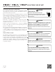
HIGH VOLTAGE !
D
ISCONNECT
ALL
POWER
BEFORE
SERVICING
.
M
ULTIPLE
POWER
SOURCES
MAY
BE
PRESENT
. F
AILURE
TO
DO
SO
MAY
CAUSE
PROPERTY
DAMAGE
,
PERSONAL
INJURY
OR
DEATH
.
WARNING
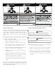
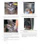
4. Remove the circuit breaker mounting bracket,
leaving the circuit breakers connected.
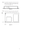
5. MBVC and MBR models
Mount the circuit breaker mounting bracket as shown
using the supplied screws. Insert two of the screws
through the blower deck from the blower side. Insert
the remaining screws in the holes provided on the
upper right side of the jacket.
CIRCUIT
BREAKER
MOUNTING
PLATE
Figure 1
NOTE: HKA-15C replaces HKR-15C and HKA-20C replaces
HKR-20C in air handlers.
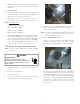
6. Insert the breaker with OFF position oriented down.
NOTE: In the horizontal position, the direction does
not matter. In some cases, it will be easier to wire
the breakers before reinserting them into the
mounting bracket.
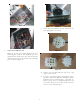
7. Insert power leads into the lugs provided on the
circuit breaker and tighten. The power leads MUST
be routed through a strain relief as they enter the
cabinet.
8. Remove the multi-pin connector with the jumper wire
and discard. Insert the one contained in the kit. It
can be inserted in one position only.
9. Insert the provided ground wire into the lug(s).
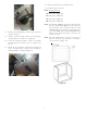
10. Remove the screws holding the clear breaker cover
and remove cover. Cut out the insulation to expose
the breaker/breakers. Reinstall the clear plastic
cover with the screws to seal opening.
11. Replace panel and check operation.
12. Apply the wiring diagram
over the one found on the
air handlers. On the “MBVC” Airhandler wiring
diagram which is included, mark an “X” on the wiring
diagram according to the number of Heater Element
rows installed.
13. If installing an HKA heater kit on a unit that only has
the corresponding HKR heater kit shown on the serial
plate, use a permanent marker to add the HKA model
to the serial plate (the data is the same as the HKR).
If the corresponding HKR model number is not on
the serial plate, the heater kit cannot be used.
T
HREE
-P
HASE
U
NIT
I
NSTALLATION
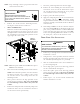
HIGH VOLTAGE !
TO
AVOID
THE
RISK
OF
ELECTRICAL
SHOCK
,
A
MEANS
OF
STRAIN
RELIEF
AND
CONDUCTOR
PROTECTION
MUST
BE
PROVIDED
AT
THE
SUPPLY
WIRE
ENTRANCE
.
WARNING
1. Follow steps 1 through 4 from “Standard Air Handler
Installation” section.
2. Using the two 1" screws provided, mount the terminal
block on the right hand side of the heater panel on
the airhandler (mounting holes are provided).
3. Wire the terminal block leads to the transformer as
per the wiring diagram.
4. Insert single phase power leads into lugs provided
on the terminal block and tighten.
5. Insert three-phase power leads into lugs provided
on the contactor and tighten. The power leads MUST
be routed through a strain relief as they enter the
cabinet.
6. Follow steps 9, 10, 11 and 12 from “Standard Air
Handler Installation” section.