
SPK Installation Instructions

2
Horizontal Models
1. Disconnect all power to the unit.
WARNING
HIGH VOLTAGE!
DISCONNECT ALL POWER BEFORE SERVICING OR INSTALLING
THIS UNIT.
MULTIPLE POWER SOURCES MAY BE PRESENT. FAILURE
TO DO SO MAY CAUSE PROPERTY DAMAGE, PERSONAL INJURY OR
DEATH.
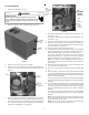
2. Remove control box door and blower door (Figure 1).
Control
Box
Door
Blower
Door
Figure 1
3. Remove cover from single point assembly.
4. Remove the 2 screws from the electric heat compartment and
use these to mount the single point assembly as shown in
Figure 2.
Use
2 screws
here to
mount plate.
Line
Voltage
Ground
Figure 2
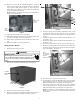
5. Bring line voltage into the blower compartment. Use the knock-
out at the left/bottom side of the blower compartment, or cut a
hole (sized correctly for the conduit being used) into the panel
on the right side of the blower compartment, just above the
electric heat compartment. See Figure 3.
-
OR -
Bring
unit harness
to control box
through
grommet
here.
Cut
appropriately
sized hole
in this area.
Use
knock-out
on the
bottom
left side
of the unit.
Cut
appropriately
sized hole
in this area.
Figure 3
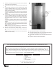
6. Connect line voltage to the middle lug (for heat pumps – L1 /
for coolers – L2).
7. Connect line voltage to the far right lug (for heat pumps – L2 /
for coolers – L1).
8. Connect the ground wire to the lug on the far left (Figure 2).
9. Route the unit wiring (the wires connected to the breaker and
the shorter green wire) into the control box through the grom-
met on the bottom. See Figure 3.
10. Connect the green wire into the ground lug.
11. For heat pumps, connect the black wires to L1 on the contactor,
and the purple wires to L2. (SPK-50 and SPK-60 will have a
black wire labeled with a #3 instead of the purple wire.)
For coolers, connect the black wires to L2 on the contactor
and the purple wires to L1. (SPK-50 and SPK-60 will have a
black wire labeled with a #3 instead of the purple wire.)
NOTE: If needed the 2 male multiplier terminals that come
with the kit can be used to create enough open terminals on
the contactor.
12. Route the remaining 4 black and one green electric heat wires
to the electric heat compartment.
13. Connect the green wire to the ground lug on the electric heat
kit.
14. For heat pumps, connect the 2 wires coming from the middle
lug on the distribution block to the L1 lugs on the breakers for
the electric heat kit (1 wire per breaker/smaller gauge wire on
smaller amperage breaker).
For coolers, connect the 2 wires to the L2 lugs on the breakers
(1 wire per breaker/smaller gauge wire on smaller amperage
breaker).
15. For heat pumps, connect the 2 wires coming from the far right
lug on the distribution block (the ends will be labeled with a
#3) to the L2 lugs on the breakers for the electric heat kit (1
wire per breaker/smaller gauge wire on smaller amperage
breaker).
For coolers, connect the 2 wires to the L1 lugs on the breakers
(1 wire per breaker/smaller gauge wire on smaller amperage
breaker).
NOTE: Circuit breaker lugs and ground lug should be torqued
to 25 - 45 IN-LBS. All wire strands should be inserted into lugs
before tightening the set screw.
NOTE: 4 wire ties have been provided in the literature bag.
Use these as needed to route / dress wires.