
SPK Installation Instructions

4
NOTE: SPECIFICATIONS AND PERFORMANCE DATA LISTED HEREIN ARE SUBJECT TO CHANGE WITHOUT NOTICE
5151 San Felipe, Suite 500, Houston, TX 77056
© 2012 - 2013 Goodman Company, L.P.
• Products
• Warranties
• Customer Services
• Parts
• Contractor Programs and Training
• Financing Options
Visit our website at www.daikincomfort.com, www.goodmanmfg.com or www.amana-hac.com for information on:
Quality Makes the Difference!
All of our systems are designed and manufactured with the same high quality standards regardless of size or effi-
ciency. We have designed these units to significantly reduce the most frequent causes of product failure. They are
simple to service and forgiving to operate. We use quality materials and components. Finally, every unit is run tested
before it leaves the factory. That’s why we know. . .There’s No Better Quality.
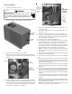
12. Route the remaining 4 black and one green electric heat wires
to the electric heat compartment.
13. Connect the green wire to the ground lug on the electric heat
kit.
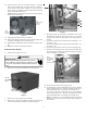
14. For heat pumps, connect the 2 wires coming from the middle
lug on the distribution block to the L1 lugs on the breakers of
the electric heat kit (1 wire per breaker/smaller gauge wire on
smaller amperage breaker).
For coolers, connect the 2 wires to the L2 lugs on the breakers
(1 wire per breaker/smaller gauge wire on smaller amperage
breaker).
15. For heat pumps, connect the 2 wires coming from the far right
lug on the distribution block (the ends will be labeled with a
#3) to the L2 lugs on the breakers of the electric heat kit (1 wire
per breaker/smaller gauge wire on smaller amperage
breaker).
For coolers, connect the 2 wires to the L1 lugs on the breakers
(1 wire per breaker/smaller gauge wire on smaller amperage
breaker).
NOTE: Circuit breaker lugs and ground lug should be torqued
to 25 - 45 IN-LBS. All wire strands should be inserted into lugs
before tightening the set screw.
NOTE: 4 wire ties have been provided in the literature bag.
Use these as needed to route / dress wires.
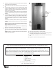
16. Place the cover on the kit as shown in Figure 8. Attach the
cover using the blunt tip screw provided with the single point
kit.
NOTE: Breaker for single point kit must be in the OFF position,
for the cover to fit correctly.
Single
Point
Breaker
Use
Blunt Tip Screw
to attach
cover here.
Figure 8
17. Flip single point breaker to the ON position.
18. Attach wiring diagram label next to the unit wiring diagram that
is located on the back of the control box door.
19. Attach blower compartment and control box door back on the
unit.
20. Begin the normal unit start-up procedures.
is a registered trademark of Maytag Corporation or its related companies and is used under license to Goodman Company, L.P.. All rights reserved.