C OM-01090-04 May 26, 1981 Rev. C 05‐31‐2013 INSTALLATION, OPERATION, AND MAINTENANCE MANUAL WITH PARTS LIST 0 SERIES PUMP MODEL 02C3-E.75 3P THE GORMAN‐RUPP COMPANY MANSFIELD, OHIO www.grpumps.com GORMAN‐RUPP OF CANADA LIMITED ST. THOMAS, ONTARIO, CANADA 1981 The Gorman‐Rupp Company Printed in U.S.A.
Register your new Gorman‐Rupp pump online at www.grpumps.com/register. Valid serial number and e‐mail address required. RECORD YOUR PUMP MODEL AND SERIAL NUMBER Please record your pump model and serial number in the spaces provided below. Your Gorman‐Rupp distributor needs this information when you require parts or service.
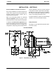
TABLE OF CONTENTS INTRODUCTION . . . . . . . . . . . . . . . . . . . . . . . . . . . . . . . . . . . . . . . . . . . . . . . . . PAGE I - 1 SAFETY - SECTION A . . . . . . . . . . . . . . . . . . . . . . . . . . . . . . . . . . . . . . . . . . . PAGE A - 1 INSTALLATION - SECTION B . . . . . . . . . . . . . . . . . . . . . . . . . . . . . . . . . . . . PAGE B - 1 Pump Dimensions . . . . . . . . . . . . . . . . . . . . . . . . . . . . . . . . . . . . . . . . . . . . . . . . . . . . .
TABLE OF CONTENTS (continued) PARTS LIST: Pump Model . . . . . . . . . . . . . . . . . . . . . . . . . . . . . . . . . . . . . . . . . . . . . . . . . . . . . . . . . . PUMP AND SEAL DISASSEMBLY AND REASSEMBLY . . . . . . . . . . . . . . . . . . . . . . . . . Pump Disassembly . . . . . . . . . . . . . . . . . . . . . . . . . . . . . . . . . . . . . . . . . . . . . . . . . . . . . Impeller Removal . . . . . . . . . . . . . . . . . . . . . . . . . . . . . . . . . . . . . . . . . . . . . . . . . . . . . .
0 SERIES OM-01090 INTRODUCTION Thank You for purchasing a Gorman‐Rupp pump. Read this manual carefully to learn how to safely install and operate your pump. Failure to do so could result in personal injury or damage to the pump. This Installation, Operation, and Maintenance manual is designed to help you achieve the best performance and longest life from your Gorman‐ Rupp pump.
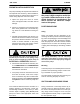
0 SERIES OM-01090 SAFETY - SECTION A This information applies to 0 Series electric motor driven pumps. Refer to the manual accompanying the motor before attempting to begin operation. This manual will alert personnel to known procedures which require spe cial attention, to those which could damage equipment, and to those which could be dangerous to personnel.
OM-01090 tional Electric Code and all local codes. If there is a conflict between the instruc tions in the manual accompanying the unit and the National Electric Code or the applicable local code, the National or local code shall take precedence. The electrical power used to operate this pump is high enough to cause inju ry or death. Obtain the services of a qu alified electrician to troubleshoot, test and/or service the electrical compo nents of this pump. 0 SERIES Never run this pump backwards.
0 SERIES OM-01090 INSTALLATION - SECTION B Review all SAFETY information in Section A. Since pump installations are seldom identical, this section offers only general recommendations and practices required to inspect, position, and ar range the pump and piping. Most of the information pertains to a standard static lift application where the pump is posi tioned above the free level of liquid to be pumped.
OM-01090 0 SERIES PREINSTALLATION INSPECTION The pump assembly was inspected and tested be fore shipment from the factory. Before installation, inspect the pump for damage which may have oc curred during shipment. Check as follows: a. Inspect the pump and motor for cracks, dents, damaged threads, and other obvious damage. b. Check for and tighten loose attaching hard ware. Since gaskets tend to shrink after dry ing, check for loose hardware at mating sur faces.
0 SERIES Materials Either pipe or hose maybe used for suction and discharge lines; however, the materials must be compatible with the liquid being pumped. If hose is used in suction lines, it must be the rigid‐wall, rein forced type to prevent collapse under suction. Us ing piping couplings in suction lines is not recom mended. Line Configuration Keep suction and discharge lines as straight as possible to minimize friction losses.
OM-01090 0 SERIES If there is a liquid flow from an open pipe into the sump, the flow should be kept away from the suc tion inlet because the inflow will carry air down into the sump, and air entering the suction line will re duce pump efficiency. If it is necessary to position inflow close to the suc tion inlet, install a baffle between the inflow and the suction inlet at a distance 1 1/2 times the diameter of the suction pipe.
0 SERIES OM-01090 A check valve in the discharge line is normally rec ommended, but it is not necessary in low dis charge head applications. With high discharge heads, it is recommended that a throttling valve and a system check valve be in stalled in the discharge line to protect the pump from excessive shock pressure and reverse rota tion when it is stopped. motor requirements stamped on the motor name plate before connecting the motor to the incoming power.
OM-01090 0 SERIES OPERATION - SECTION C Review all SAFETY information in Section A. Follow the instructions on all tags, labels and decals attached to the pump. This pump is designed to handle clean liquids that do not contain large en trained solids. Do not attempt to pump volatile, corrosive, or flammable liquids which may damage the pump or endan ger personnel as a result of pump fail ure. Pump speed and operating conditions must be within the performance range shown on page E‐1.
OM-01090 0 SERIES three phase wires to change direction. If rotation is incorrect on a single‐phase motor, consult the liter ature supplied with the motor for specific instruc tions. pressure, and cause the pump casing to rupture or explode. OPERATION No leakage should be visible at pump mating sur faces, or at pump connections or fittings. Keep all line connections and fittings tight to maintain maxi mum pump efficiency.
OM-01090 0 SERIES Never introduce air or steam pressure into the pump casing or piping to remove a blockage. This could result in personal injury or damage to the equipment. If backflushing is absolutely neces sary, liquid pressure must be limited to 50% of the maximum permissible operating pressure shown on the pump performance curve. Pump Vacuum Check With the pump inoperative, install a vacuum gauge in the system, using pipe dope on the threads. Block the suction line and start the pump.
0 SERIES OM-01090 TROUBLESHOOTING - SECTION D Review all SAFETY information in Section A. Before attempting to open or service the pump: 1. Familiarize yourself with this manual. 2. Disconnect the incoming power to the motor and lock it out to ensure that the pump will remain inopera tive. 3. Allow the pump to completely cool if overheated. 4. Check the temperature before open ing any covers, plates, or plugs. 5. Close the suction and discharge valves. 6. Vent the pump slowly and cautiously. 7.
OM-01090 0 SERIES TROUBLE POSSIBLE CAUSE PROBABLE REMEDY PUMP STOPS OR FAILS TO DELIVER RATED FLOW OR PRESSURE (cont.) Strainer clogged. Check strainer and clean if neces sary. Check installation and correct sub mergence as needed. Suction intake not submerged at proper level or sump too small. Impeller or other wearing parts worn or damaged. Replace worn or damaged parts. Check that impeller is properly centered and rotates freely. Impeller clogged. Free impeller of debris.
0 SERIES OM-01090 PREVENTIVE MAINTENANCE Since pump applications are seldom identical, and pump wear is directly affected by such things as the abrasive qualities, pressure and temperature of the liquid being pumped, this section is intended only to provide general recommendations and practices for preventive maintenance. Regardless of the application however, following a routine pre ventive maintenance schedule will help assure trouble‐free performance and long life from your Gorman‐Rupp pump.
OM-01090 0 SERIES PUMP MAINTENANCE AND REPAIR - SECTION E MAINTENANCE AND REPAIR OF THE WEARING PARTS OF THE PUMP WILL MAINTAIN PEAK OPERATING PERFORMANCE. STANDARD PERFORMANCE FOR PUMP MODELS 02C3-E.75 3P Based on 70 F (21 C) clear water at sea level with minimum suction lift. Since pump installations are seldom identical, your performance may be dif ferent due to such factors as viscosity, specific gravity, elevation, temperature, and impeller trim.
OM-01090 0 SERIES SECTION DRAWING PARTS PAGE Figure 1. Pump Models 02C3-E.
OM-01090 0 SERIES PARTS LIST Pump Models 02C3-E.75 3P (From S/N 241492N Up) If your pump serial number is followed by an “N”, your pump is NOT a standard production model. Contact the Gorman‐Rupp Company to verify part numbers. ITEM NO.
OM-01090 PUMP AND SEAL DISASSEMBLY AND REASSEMBLY Review all SAFETY information in Section A. Follow the instructions on all tags, label and decals attached to the pump. This pump requires little service due to its rugged, minimum‐maintenance design. However, if it be comes necessary to inspect or replace the wearing parts, follow these instructions which are keyed to the sectional view (see Figure 1) and the accompa nying parts list.
0 SERIES Immobilize the motor shaft by inserting a large flat head screwdriver into the slot in the end of the shaft in the front end of the motor. Unscrew the impeller from the shaft. Use caution when removing the impeller; tension on the seal spring will be released as the impeller is removed. Remove the impeller adjusting shims (14). Tie and tag the shims or measure and record their thick ness for ease of reassembly. OM-01090 flammable.
OM-01090 0 SERIES RETAINER SEAL PLATE SPRING IMPELLER STATIONARY ELEMENT IMPELLER SHIMS IMPELLER SHAFT BELLOWS SPRING RETAINER DRIVE BAND ROTATING ELEMENT STATIONARY SEAT Figure 2. Seal Assembly Subassemble the rotating element into the retainer and bellows. Lubricate the I.D. of the bellows with water and slide this subassembly onto the shaft until the polished faces contact. Install the seal operation at spring and spring retainer. This seal is not designed for temperatures above 160 F (71 C).
0 SERIES OM-01090 C D D 2 B 2 A E B Step 1 Step 2 A+ B 2 - C+ D 2 Step 3 =E Figure 3. Centering Impeller Within Vane Plate Scroll Install the correct thickness of impeller shims (14) and screw the impeller onto the shaft until fully seated. Apply “Loctite Threadlocker No. 242” or equivalent compound to the impeller shaft threads. Immobi lize the motor shaft by inserting a large flat head screwdriver into the slot in the end of the shaft in the front end of the motor.
For U.S. and International Warranty Information, Please Visit www.grpumps.com/warranty or call: U.S.: 419-755-1280 International: +1-419-755-1352 For Canadian Warranty Information, Please Visit www.grcanada.com/warranty or call: 519-631-2870 THE GORMAN‐RUPP COMPANY MANSFIELD, OHIO GORMAN‐RUPP OF CANADA LIMITED ST.