ACE OM-02818-OB02 September 11, 2000 INSTALLATION, OPERATION, AND MAINTENANCE MANUAL WITH PARTS LIST VG SERIES PUMP MODEL VG6E3−B THE GORMAN-RUPP COMPANY MANSFIELD, OHIO www.grpumps.com GORMAN-RUPP OF CANADA LIMITED ST. THOMAS, ONTARIO, CANADA Copyright by the Gorman-Rupp Company Printed in U.S.A.
Register your new Gorman-Rupp pump online at www.grpumps.com Valid serial number and e-mail address required. RECORD YOUR PUMP MODEL AND SERIAL NUMBER Please record your pump model and serial number in the spaces provided below. Your Gorman-Rupp distributor needs this information when you require parts or service.
TABLE OF CONTENTS INTRODUCTION . . . . . . . . . . . . . . . . . . . . . . . . . . . . . . . . . . . . . . . . . . . . . . . . . PAGE I − 1 WARNINGS − SECTION A . . . . . . . . . . . . . . . . . . . . . . . . . . . . . . . . . . . . . . . PAGE A − 1 INSTALLATION − SECTION B . . . . . . . . . . . . . . . . . . . . . . . . . . . . . . . . . . . . PAGE B − 1 Pump Dimensions . . . . . . . . . . . . . . . . . . . . . . . . . . . . . . . . . . . . . . . . . . . . . . . . . . . . .
TABLE OF CONTENTS (continued) PUMP MAINTENANCE AND REPAIR − SECTION E . . . . . . . . . . . . . . . . STANDARD PERFORMANCE CURVE . . . . . . . . . . . . . . . . . . . . . . . . . . . . . . . . . . . . . . . . PUMP MODEL − PARTS LIST . . . . . . . . . . . . . . . . . . . . . . . . . . . . . . . . . . . . . . . . . . . . . . . PUMP AND SEAL DISASSEMBLY AND REASSEMBLY . . . . . . . . . . . . . . . . . . . . . . . . . Impeller Removal . . . . . . . . . . . . . . . . . . . . . . . . . . . . . . . . . . . . . . .
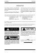
VG SERIES OM−02818 INTRODUCTION This Installation, Operation, and Maintenance manual is designed to help you achieve the best performance and longest life from your GormanRupp pump. suction check valve. The pump is designed for high pressure distribution of liquids containing specified entrained solids. The basic material of construction for wetted parts is gray iron. Be sure the liquid being pumped is compatible with this material.
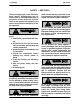
VG SERIES OM−02818 SAFETY − SECTION A These warnings apply to the VG Series basic pumps. Gorman-Rupp has no control over or particular knowledge of the power source which will be used. Refer to the manual accompanying the power source before attempting to begin operation. Before attempting to open or service the pump: 1. Familiarize yourself with this manual. 2. Disconnect or lock out the power source to ensure that the pump will remain inoperative. 3. Allow the pump to completely cool if overheated. 4.
VG SERIES OM−02818 INSTALLATION − SECTION B Review all SAFETY information in Section A. Since pump installations are seldom identical, this section offers only general recommendations and practices required to inspect, position, and arrange the pump and piping. Most of the information pertains to a standard static lift application where the pump is positioned above the free level of liquid to be pumped. configuration, and priming must be tailored to the specific application.
OM−02818 PREINSTALLATION INSPECTION VG SERIES POSITIONING PUMP Lifting The pump assembly was inspected and tested before shipment from the factory. Before installation, inspect the pump for damage which may have occurred during shipment. Check as follows: a. Inspect the pump for cracks, dents, damaged threads, and other obvious damage. b. Check for and tighten loose attaching hardware. Since gaskets tend to shrink after drying, check for loose hardware at mating surfaces. c.
VG SERIES mum use of elbows and fittings, which substantially increase friction loss. If elbows are necessary, use the long-radius type to minimize friction loss. Connections to Pump Before tightening a connecting flange, align it exactly with the pump port. Never pull a pipe line into place by tightening the flange bolts and/or couplings.
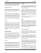
OM−02818 tance equal to at least 3 times the diameter of the suction pipe. Suction Line Positioning The depth of submergence of the suction line is critical to efficient pump operation. Figure 2 shows recommended minimum submergence vs. velocity. VG SERIES NOTE The pipe submergence required may be reduced by installing a standard pipe increaser fitting at the end of the suction line. The larger opening size will reduce the inlet velocity.
VG SERIES OM−02818 ALIGNMENT The alignment of the pump and its power source is critical for trouble-free mechanical operation. In either a flexible coupling or V-belt driven system, the driver and pump must be mounted so that their shafts are aligned with and parallel to each other. It is imperative that alignment be checked after the pump and piping are installed, and before operation. of the outer ends of the coupling hub every 90 degrees.
OM−02818 VG SERIES Tighten the belts in accordance with the belt manufacturer’s instructions. If the belts are too loose, they will slip; if the belts are too tight, there will be excessive power loss and possible bearing failure. Select pulleys that will match the proper speed ratio; overspeeding the pump may damage both pump and power source. MISALIGNED: SHAFTS NOT PARALLEL MISALIGNED: SHAFTS NOT IN LINE ALIGNED: SHAFTS PARALLEL AND SHEAVES IN LINE Figure 3C.
OM−02818 VG SERIES OPERATION − SECTION C Review all SAFETY information in Section A. Follow the instructions on all tags, labels and decals attached to the pump. This pump is designed to handle liquids containing specified entrained solids. Do not attempt to pump volatile, corrosive, or flammable liquids which may damage the pump or endanger personnel as a result of pump failure. Pump speed and operating conditions must be within the performance range shown on page E-1.
OM−02818 a venturi which creates a vacuum in the pump casing in order to fill the suction line and pump casing with liquid. To prime a pump using an exhaust primer, open the gas cock in the priming line and engage the exhaust primer until liquid is thrown out of the ejector nozzle. VG SERIES Rotation The correct direction of pump rotation is counterclockwise when facing the impeller.
OM−02818 VG SERIES against closed valves could bring the liquid to a boil, build pressure, and cause the pump to rupture or explode. If overheating occurs, stop the pump and allow it to cool before servicing it. Refill the pump casing with cool liquid. Allow an over-heated pump to cool before servicing. Do not remove plates, covers, gauges, or fittings from an overheated pump.
OM−02818 BEARING TEMPERATURE CHECK Bearings normally run at higher than ambient temperatures because of heat generated by friction. Temperatures up to 160 F (71,1 C) are considered normal for bearings, and they can operate safely to at least 180 F (82,2 C). Checking bearing temperatures by hand is inaccurate. Bearing temperatures can be measured accurately by placing a contact-type thermometer against the housing. Record this temperature for future reference.
VG-SERIES OM−02818 TROUBLESHOOTING − SECTION D Review all SAFETY information in Section A. Before attempting to open or service the pump: 1. Familiarize yourself with this manual. 2. Lock out or disconnect the power source to ensure that the pump will remain inoperative. 3. Allow the pump to completely cool if overheated. 4. Check the temperature before opening any covers, plates, or plugs. 5. Close the suction and discharge valves. 6. Vent the pump slowly and cautiously. 7. Drain the pump.
OM−02818 VG-SERIES TROUBLE POSSIBLE CAUSE PROBABLE REMEDY PUMP STOPS OR FAILS TO DELIVER RATED FLOW OR PRESSURE (cont.) Discharge throttling valve partially closed; check that valve is installed improperly. Open discharge valve fully; check piping installation. Pump speed too slow. Check driver output; check belts or couplings for slippage. Suction lift too high. Measure lift w/vacuum gauge. Reduce lift and/or friction losses in suction line. Leaking or worn seal or pump gasket.
VG-SERIES OM−02818 TROUBLE POSSIBLE CAUSE PROBABLE REMEDY BEARINGS RUN TOO HOT Bearing temperature is high, but within limits. Check bearing temperature regularly to monitor any increase. Low or incorrect lubricant. Check for proper type and level of lubricant. Pump speed too high. Reduce speed of power source.
OM−02818 VG-SERIES Preventive Maintenance Schedule Service Interval* Item General Condition (Temperature, Unusual Noises or Vibrations, Cracks, Leaks, Loose Hardware, Etc.
VG SERIES OM−02818 PUMP MAINTENANCE AND REPAIR − SECTION E MAINTENANCE AND REPAIR OF THE WEARING PARTS OF THE PUMP WILL MAINTAIN PEAK OPERATING PERFORMANCE. STANDARD PERFORMANCE FOR PUMP MODEL VG6E3−B Based on 70 F (21,1 C) clear water at sea level with minimum suction lift. Since pump installations are seldom identical, your performance may be different due to such factors as viscosity, specific gravity, elevation, temperature, and impeller trim.
OM−02818 VG SERIES SECTION DRAWING PARTS PAGE Figure 1.
VG SERIES OM−02818 PARTS LIST Pump Model VG6E3−B (From S/N 1238969 up) If your pump serial number is followed by an N", your pump is NOT a standard production model. Contact the Gorman-Rupp Company to verify part numbers. ITEM PART NAME NO.
OM−02818 PUMP AND SEAL DISASSEMBLY AND REASSEMBLY Review all SAFETY information in Section A. VG SERIES 5. Close the suction and discharge valves. 6. Vent the pump slowly and cautiously. 7. Drain the pump. Follow the instructions on all tags, label and decals attached to the pump. This pump requires little service due to its rugged, minimum-maintenance design.
VG SERIES OM−02818 under the bellows. Slide the rotating element, retainer and bellows, spring, and spring holder off the sleeve. NOTE It is not necessary to remove the seal collar (6) unless the collar or sleeve requires replacement. DO NOT remove the collar until the exact location has been recorded either by scribing or measurement. The location of the collar is critical to pump operation since it establishes the working length of the seal.
OM−02818 ly shorten bearing life. Do not spin dry bearings. This may scratch the balls, rollers or races and cause premature bearing failure. The roller bearing tolerances provide a tight press fit onto the shaft and a snug slip fit into the bearing housing. The ball bearing provides a tight press fit into the bearing housing and snug slip onto the shaft. Replace the bearings, shaft, or bearing housing if the proper bearing fit is not achieved.
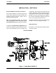
VG SERIES OM−02818 faces to ensure that they are free of any foreign matter. sleeve, O-rings and bellows with water or a very small amount of oil, and apply a drop of light lubricating oil on the finished faces. Assemble the seal as follows, (see Figure 2). To ease installation of the seal, lubricate the shaft RETAINER SPRING CENTERING WASHER BELLOWS A O-RING SPRING STATIONARY ELEMENT SHAFT SLEEVE O-RING IMPELLER SHAFT SEAL COLLAR SEAL CAP SETSCREW ROTATING ELEMENT SEAL PLATE Figure 2.
OM−02818 Slide the seal plate, shaft sleeve and seal assembly onto the shaft. Secure the seal plate to the bearing housing with the nuts (15). Impeller Installation Inspect the impeller, and replace it if cracked or badly worn. Install the impeller key (46) and slide the impeller onto the shaft and against the sleeve until both are fully seated. Install the impeller nut (47). Install the seal plate gasket (10). Slide the pump casing (1) over the impeller and secure it to the seal plate with the nuts (13).
For U.S. and International Warranty Information, Please Visit www.grpumps.com/warranty or call: U.S.: 419−755−1280 International: +1−419−755−1352 For Canadian Warranty Information, Please Visit www.grcanada.com/warranty or call: 519−631−2870 THE GORMAN-RUPP COMPANY D MANSFIELD, OHIO GORMAN-RUPP OF CANADA LIMITED D ST.