ACE OM-06122−02 May 9, 2008 INSTALLATION, OPERATION, AND MAINTENANCE MANUAL WITH PARTS LIST VGH SERIES PUMP MODEL VGH2 1/2D31−B THE GORMAN-RUPP COMPANY D MANSFIELD, OHIO www.grpumps.com GORMAN-RUPP OF CANADA LIMITED D ST. THOMAS, ONTARIO, CANADA e2008 The Gorman-Rupp Company Printed in U.S.A.
Register your new Gorman-Rupp pump online at www.grpumps.com Valid serial number and e-mail address required. RECORD YOUR PUMP MODEL AND SERIAL NUMBER Please record your pump model and serial number in the spaces provided below. Your Gorman-Rupp distributor needs this information when you require parts or service.
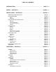
TABLE OF CONTENTS INTRODUCTION . . . . . . . . . . . . . . . . . . . . . . . . . . . . . . . . . . . . . . . . . . . . . . . . . PAGE I − 1 SAFETY - SECTION A . . . . . . . . . . . . . . . . . . . . . . . . . . . . . . . . . . . . . . . . . . . . PAGE A − 1 INSTALLATION − SECTION B . . . . . . . . . . . . . . . . . . . . . . . . . . . . . . . . . . . . PAGE B − 1 PREINSTALLATION INSPECTION . . . . . . . . . . . . . . . . . . . . . . . . . . . . . . . . . . . . . . . . . . . . POSITIONING PUMP . . . .
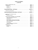
TABLE OF CONTENTS (continued) BEARING TEMPERATURE CHECK . . . . . . . . . . . . . . . . . . . . . . . . . . . . . . . . . . . . . . . . . . LUBRICATION . . . . . . . . . . . . . . . . . . . . . . . . . . . . . . . . . . . . . . . . . . . . . . . . . . . . . . . . . . . . . Seal Assembly . . . . . . . . . . . . . . . . . . . . . . . . . . . . . . . . . . . . . . . . . . . . . . . . . . . . . . . . . Bearings . . . . . . . . . . . . . . . . . . . . . . . . . . . . . . . . . . . . . . . . . . . . . . . . . . .
VGH SERIES OM−06122 INTRODUCTION Thank You for purchasing a Gorman-Rupp pump. Read this manual carefully to learn how to safely install and operate your pump. Failure to do so could result in personal injury or damage to the pump. This manual will alert personnel to known procedures which require special attention, to those which could damage equipment, and to those which could be dangerous to personnel.
VGH SERIES OM−06122 SAFETY - SECTION A This information applies to VGH Series basic pumps. Gorman-Rupp has no control over or particular knowledge of the power source which will be used. Refer to the manual accompanying the power source before attempting to begin operation. Because pump installations are seldom identical, this manual cannot possibly provide detailed instructions and precautions for each specific application.
OM−06122 If this pump is used with volatile and/or flammable liquids, overheating may produce dangerous fumes. Take precautions to ensure the area surrounding the pump is adequately ventilated. Allow the pump to cool and use extreme caution when venting the pump, or when removing covers, plates, plugs, or fittings. VGH SERIES of time.
VGH SERIES OM−06122 INSTALLATION − SECTION B Review all SAFETY information in Section A. Since pump installations are seldom identical, this section offers only general recommendations and practices required to inspect, position, and arrange the pump and piping. Most of the information pertains to a standard static lift application where the pump is positioned above the free level of liquid to be pumped.
OM−06122 Mounting Locate the pump in an accessible place as close as practical to the liquid being pumped. Level mounting is essential for proper operation. The pump may have to be supported or shimmed to provide for level operation or to eliminate vibration. SUCTION AND DISCHARGE PIPING Materials Either pipe or hose maybe used for suction and discharge lines; however, the materials must be compatible with the liquid being pumped.
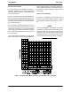
VGH SERIES Suction Lines In Sumps If a single suction line is installed in a sump, it should be positioned away from the wall of the sump at a distance equal to 1 1/2 times the diameter of the suction line. If there is a liquid flow from an open pipe into the sump, the flow should be kept away from the suction inlet because the inflow will carry air down into the sump, and air entering the suction line will reduce pump efficiency.
OM−06122 DISCHARGE LINES VGH SERIES FILL ONLY THROUGH CONSTANT LEVEL OILER Siphoning Do not terminate the discharge line at a level lower than that of the liquid being pumped unless a siphon breaker is used in the line. Otherwise, a siphoning action causing damage to the pump could result. DO NOT FILL THROUGH VENT PLUG Figure 2. Lubricating Bearing Cavity Valves If a throttling valve is desired in the discharge line, use a valve as large as the largest pipe to minimize friction losses.
VGH SERIES OM−06122 When checking alignment, disconnect the power source to ensure that the pump will remain inoperative. Adjusting the alignment in one direction may alter the alignment in another direction. check each procedure after altering alignment. Coupled Drives When using couplings, the axis of the power source must be aligned to the axis of the pump shaft in both the horizontal and vertical planes. Most couplings require a specific gap or clearance between the driving and the driven shafts.
OM−06122 VGH SERIES The electrical power used to operate the pump is high enough to cause injury or death. Obtain the services of a qualified electrician to make all electrical connections. MISALIGNED: SHAFTS NOT PARALLEL MISALIGNED: SHAFTS NOT IN LINE ALIGNED: SHAFTS PARALLEL AND SHEAVES IN LINE Figure 3C. Alignment of V-Belt Driven Pumps Tighten the belts in accordance with the belt manufacturer’s instructions.
OM−06122 VGH SERIES OPERATION − SECTION C Review all SAFETY information in Section A. PRIMING Follow the instructions on all tags, labels and decals attached to the pump. Install the pump and piping as described in INSTALLATION. Make sure that the piping connections are tight, and that the pump is securely mounted. Check that the pump is properly lubricated (see LUBRICATION in the MAINTENANCE AND REPAIR manual).
OM−06122 suction line and pump casing. To prime a pump with a hand vacuum pump, open the cock on the pump priming line. Operate the hand pump until liquid flows out of the check valve on the bottom of the primer pump. Once the pump is primed, close the valve located between the primer and the pump so that the prime will not be lost. VGH SERIES Auxiliary Ejectors Ejectors function much like exhaust primers. They may be operated by steam, compressed air, water or exhaust gases.
OM−06122 VGH SERIES OPERATION If overheating does occur, stop the pump immediately and allow it to cool before servicing it. Approach any overheated pump cautiously. Strainer Check Pump speed and operating points must be within the continuous performance range shown on the pump curve (see page E−1). Leakage No leakage should be visible at pump mating surfaces, or at pump connections or fittings. Keep all line connections and fittings tight to maintain maximum pump efficiency.
OM−06122 VGH SERIES BEARING TEMPERATURE CHECK To avoid serious damage to the pump, check for unusual noises or excessive vibration while the pump is running. If noise or vibration is excessive, stop operation and refer to the TROUBLESHOOTING, Section D, before resuming operation. STOPPING Never halt the flow of liquid suddenly. If the liquid being pumped is stopped abruptly, damaging shock waves can be transmitted to the pump and piping system. Close all connecting valves slowly.
OM−06122 VGH SERIES uid from an external source. When handling clean liquids, flushing liquid is taken from the pump discharge and supplied through the seal flush line supplied with the pump. When handling abrasive or tacky liquids, it may be necessary to supply fresh lubricating liquid from an external source. Be sure the liquid supplied to the seal is compatible with the liquid being pumped, and that its flow is controlled to prevent dilution. Consult the factory if flushing is required.
VGH SERIES OM−06122 TROUBLESHOOTING − SECTION B Review all SAFETY information in Section A. Before attempting to open or service the pump: 1. Familiarize yourself with this manual. 2. Lock out or disconnect the power source and take the necessary precautions to ensure that the pump will remain inoperative. 3. Allow the pump to completely cool if overheated. 4. Check the temperature before opening any covers, plates, or plugs. 5. Close the suction and discharge valves. 6.
OM−06122 VGH SERIES Table D-1 Troubleshooting Chart (Continued) TROUBLE PUMP STOPS OR FAILS TO DELIVER RATED FLOW OR PRESSURE (cont.) POSSIBLE CAUSE PROBABLE REMEDY Impeller or other wearing parts worn Replace worn or damaged parts. or damaged. Check that impeller is properly centered and rotates freely. Leaking or worn seal or pump gas- Check pump vacuum. Replace leakket. ing or worn seal or gasket. Impeller clogged. Free impeller of debris.
VGH SERIES OM−06122 Table D-1 Troubleshooting Chart (Continued) TROUBLE BEARINGS RUN TOO HOT POSSIBLE CAUSE Bearing temperature is high, but Check bearing temperature regularly within limits. to monitor any increase Low or incorrect lubricant.
OM−06122 VGH SERIES Preventive Maintenance Schedule Service Interval* Item General Condition (Temperature, Unusual Noises or Vibrations, Cracks, Leaks, Loose Hardware, Etc.
VGH SERIES OM−06122 PUMP MAINTENANCE AND REPAIR - SECTION E MAINTENANCE AND REPAIR OF THE WEARING PARTS OF THE PUMP WILL MAINTAIN PEAK OPERATING PERFORMANCE. STANDARD PERFORMANCES FOR PUMP MODEL VGH2 1/2D31−B Based on 70_ F (21_ C) clear water at sea level with minimum suction lift. Since pump installations are seldom identical, your performance may be difference due to such factors as viscosity, specific gravity, elevation, temperature, and impeller trim.
OM−06122 VGH SERIES SECTION DRAWING PARTS PAGE Figure 1.
VGH SERIES OM−06122 PARTS LIST Pump Assembly VGH2 1/2D31−B (From S/N 1379872 Up) If your pump serial number is followed by an N", your pump is NOT a standard production model. Contact the Gorman-Rupp Company to verify part numbers. ITEM PART NAME NO.
OM−06122 PUMP AND SEAL DISASSEMBLY AND REASSEMBLY Review all Safety information in Section A. Follow the instructions on all tags, label and decals attached to the pump. This pump requires little service due to its rugged, minimum-maintenance design. However, if it becomes necessary to inspect or replace the wearing parts, follow these instructions which are keyed to the sectional view (see Figure 1) and the accompanying parts list.
VGH SERIES OM−06122 move the seal plate gasket (41) and clean the mating surfaces. Immobilize the impeller shaft (20). Remove the impeller hardware (45, 46, 47 and 50). Using a softfaced mallet, tap the impeller from the shaft. Retain the impeller key (51). Inspect the impeller and replace it if cracked or badly worn. Shaft and bearing disassembly in the field is not recommended. These operations should be performed only in a properlyequipped shop by qualified personnel.
OM−06122 Clean the bearing housing, shaft and all component parts (except the bearings) with a soft cloth soaked in cleaning solvent. Inspect the parts for wear or damage and replace as necessary. VGH SERIES oven, or hot plate may be used to heat the bearing. Bearings should never be heated with a direct flame or directly on a hot plate. NOTE Most cleaning solvents are toxic and flammable. Use them only in a well ventilated area free from excessive heat, sparks, and flame.
VGH SERIES Press the oil seal (23) into the bearing cover (25) with the lip positioned as shown in Figure 1. Install the gasket (26) and secure the bearing cover to the bearing housing (15) with the capscrews (20). Position the bearing housing on a secure work surface with the seal plate end facing up. Press the outer ring and rollers of the inboard bearing (31) into the bearing housing until fully seated.
OM−06122 VGH SERIES Do not attempt to separate the seal, this could damage the seal. Individual parts are not sold separately. If a replacement seal is being used, remove it from the container and inspect it to ensure that it is free of any foreign matter. Inspect the seal for wear, scoring, grooves, and other damage that might cause leakage. If any components are worn, replace the seal.
VGH SERIES OM−06122 sleeve is just flush with the shaft shoulder. Secure the sleeve to the shaft with the setscrew (54). Install a new gasket (38) in the step on the front of the seal flange. Align the studs (9 and 36) with the holes in the bearing housing and seal flange and slide the seal plate (39) over the shaft until the step on the O.D. of the seal plate is fully seated in the bearing housing. Make sure the coupling (5) in the seal flange is properly aligned for installation of the vent line (8).
OM−06122 Do not fill the bearing cavity through the vent plug in the top of the housing. This will result in over-filling, and can cause leakage, excessive heat buildup and/or premature bearing failure. Check the oil level regularly through the constant level oiler and add oil as required. Under normal conditions, drain the bearing housing once each year and refill with clean oil.
For U.S. and International Warranty Information, Please Visit www.grpumps.com/warranty or call: U.S.: 419−755−1280 International: +1−419−755−1352 For Canadian Warranty Information, Please Visit www.grcanada.com/warranty or call: 519−631−2870 THE GORMAN-RUPP COMPANY D MANSFIELD, OHIO GORMAN-RUPP OF CANADA LIMITED D ST.