CDS OM-06012-02 April 16, 2007 Rev. B 12‐14‐12 INSTALLATION, OPERATION, AND MAINTENANCE MANUAL WITH PARTS LIST ULTRA V PUMP MODEL VS3A60-B INCLUDING: /WW THE GORMAN‐RUPP COMPANY MANSFIELD, OHIO www.grpumps.com GORMAN‐RUPP OF CANADA LIMITED ST. THOMAS, ONTARIO, CANADA 2007 The Gorman‐Rupp Company Printed in U.S.A.
Register your new Gorman‐Rupp pump online at www.grpumps.com Valid serial number and e‐mail address required. RECORD YOUR PUMP MODEL AND SERIAL NUMBER Please record your pump model and serial number in the spaces provided below. Your Gorman‐Rupp distributor needs this information when you require parts or service.
TABLE OF CONTENTS INTRODUCTION . . . . . . . . . . . . . . . . . . . . . . . . . . . . . . . . . . . . . . . . . . . . . . . . . PAGE I - 1 SAFETY - SECTION A . . . . . . . . . . . . . . . . . . . . . . . . . . . . . . . . . . . . . . . . . . . PAGE A - 1 INSTALLATION - SECTION B . . . . . . . . . . . . . . . . . . . . . . . . . . . . . . . . . . . . PAGE B - 1 Pump Dimensions . . . . . . . . . . . . . . . . . . . . . . . . . . . . . . . . . . . . . . . . . . . . . . . . . . . . .
TABLE OF CONTENTS (continued) Pump Vacuum Check . . . . . . . . . . . . . . . . . . . . . . . . . . . . . . . . . . . . . . . . . . . . . . . . . . STOPPING . . . . . . . . . . . . . . . . . . . . . . . . . . . . . . . . . . . . . . . . . . . . . . . . . . . . . . . . . . . . . . . . Cold Weather Preservation . . . . . . . . . . . . . . . . . . . . . . . . . . . . . . . . . . . . . . . . . . . . . . BEARING TEMPERATURE CHECK . . . . . . . . . . . . . . . . . . . . . . . . . . . . . . . . . . . . . . . . . .
ULTRA V SERIES OM-06012 INTRODUCTION Thank You for purchasing a Gorman‐Rupp pump. Read this manual carefully to learn how to safely install and operate your pump. Failure to do so could result in personal injury or damage to the pump.
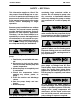
ULTRA V SERIES OM-06012 SAFETY - SECTION A This information applies to Ultra V Se ries pumps. Gorman‐Rupp has no con trol over or particular knowledge of the power source which will be used. Refer to the manual accompanying the power source before attempting to begin operation. Because pump installations are seldom identical, this manual cannot possibly provide detailed instructions and pre cautions for each specific application.
OM-06012 ULTRA V SERIES Use lifting and moving equipment in good repair and with adequate capacity to prevent injuries to personnel or dam age to equipment. Suction and dis charge hoses and piping must be re moved from the pump before lifting. Do not attempt to disengage any part of an overheated pump unit. Vapor pres sure within the pump casing can eject these parts with great force when they are disengaged. Allow the pump to completely cool before servicing it.
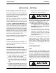
ULTRA V SERIES OM-06012 INSTALLATION - SECTION B Review all SAFETY information in Section A. Check that the pump shaft rotates counter clockwise when facing the impeller. Since pump installations are seldom identical, this section offers only general recommendations and practices required to inspect, position, and ar range the pump and piping. Most of the information pertains to a standard static lift application where the pump is posi tioned above the free level of liquid to be pumped.
OM-06012 and move the unit are improperly wrapped around the pump. Mounting Locate the pump in an accessible place as close as practical to the liquid being pumped. Level mount ing is essential for proper operation. The pump may have to be supported or shimmed to provide for level operation or to eliminate vibra tion. Clearance It is recommended that 18 inches (457 mm) of clearance be provided in front of the back cover to permit removal of the cover and easy access to the pump interior.
ULTRA V SERIES strainer furnished with the pump will also pass through the pump itself. If a strainer is not furnished with the pump, but is installed by the pump user, make certain that the total area of the openings in the strainer is at least three or four times the cross section of the suction line, and that the openings will not permit passage of solids larger than the solids handling capability of the pump. This pump is designed to handle up to 2-1/2 inch (63,5 mm) diameter spherical solids.
OM-06012 ULTRA V SERIES Figure 1. Recommended Minimum Suction Line Submergence vs. Velocity Siphoning If a throttling valve is desired in the discharge line, use a valve as large as the largest pipe to minimize friction losses. Never install a throttling valve in a suction line. Do not terminate the discharge line at a level lower than that of the liquid being pumped unless a si phon breaker is used in the line. Otherwise, a si phoning action causing damage to the pump could result.
ULTRA V SERIES OM-06012 affect pump discharge capacity; however, the by pass line should be at least 1 inch in diameter to minimize the chance of plugging. In low discharge head applications (less than 30 feet or 9 meters), it is recommended that the by pass line be run back to the wet well, and located 6 inches below the water level or cut‐off point of the low level pump. In some installations, this bypass line may be terminated with a six‐to‐eight foot length of 1-1/4 inch I.D.
OM-06012 ULTRA V SERIES Air Release Valve Installation Staged pump applications generate much higher operating pressures within the pump casings than non‐staged pump applications. This high pressure could cause a suction check valve to fail, resulting in loss of prime. Therefore, any pump used in a staged application, whether in the lower or up per position, must have the suction check valve removed.
ULTRA V SERIES OM-06012 dard 1‐inch NPT fitting, or the Air Release Valve may be installed in a spool flange between the two dis charge check valves. stage pump motor “ramping down” and shutting off. This “ramp up” and “ramp down” configuration helps reduce inrush current on startup and de structive “water hammer” on both startup and shut down. Connect the valve outlet to a bleed line which slopes back to the wet well or sump.
OM-06012 ULTRA V SERIES Figure 5 shows a recommended alternate single motor belt drive arrangement where the both pump shafts are driven by separate drive belts con nected to one motor. In this arrangement, shaft and/or bearing loads are evenly divided between the two pumps. Figure 6.
ULTRA V SERIES OM-06012 either a flexible coupling or belt‐driven system, the driver and pump must be mounted so that their shafts are aligned with and parallel to each other. It is imperative that alignment be checked after the pump and piping are installed, and before opera tion. NOTE Check Rotation, Section C, before final alignment of the pump. Figure 8.
OM-06012 ULTRA V SERIES Figure 9. Aligning Spider‐Type Couplings MISALIGNED: SHAFTS NOT PARALLEL MISALIGNED: SHAFTS NOT IN LINE ALIGNED: SHAFTS PARALLEL AND SHEAVES IN LINE Figure 11. Alignment of V‐Belt Driven Pumps Tighten the belts in accordance with the belt manu facturer's instructions. If the belts are too loose, they will slip; if the belts are too tight, there will be excessive power loss and possible bearing failure.
OM-06012 ULTRA V SERIES OPERATION - SECTION C Review all SAFETY information in Section A. Follow the instructions on all tags, labels and de cals attached to the pump. This pump is designed to handle liquids containing large entrained solids and slurries. Do not attempt to pump vola tile, corrosive, or flammable liquids which may damage the pump or endan ger personnel as a result of pump fail ure. Pump speed and operating conditions must be within the performance range shown on pages E‐1.
OM-06012 If rotation is incorrect on a three‐phase motor, have a qualified electrician interchange any two of the three phase wires to change direction. If rotation is incorrect on a single‐phase motor, consult the liter ature supplied with the motor for specific instruc tions. ULTRA V SERIES pump components will deteriorate, and the liquid could come to a boil, build pressure, and cause the pump casing to rupture or explode.
OM-06012 ULTRA V SERIES heated pump cautiously. It is recommended that the pressure relief valve assembly be replaced at each overhaul, or any time the pump casing over heats and activates the valve. Never replace this valve with a substitute which has not been speci fied or provided by the Gorman‐Rupp Company. Strainer Check If a suction strainer has been shipped with the pump or installed by the user, check the strainer regularly, and clean it as necessary.
OM-06012 ULTRA V SERIES Checking bearing temperatures by hand is inaccu rate. Bearing temperatures can be measured ac curately by placing a contact‐type thermometer against the housing. Record this temperature for future reference. rect level (see LUBRICATION in MAINTENANCE AND REPAIR). Bearing overheating can also be caused by shaft misalignment and/or excessive vi bration. A sudden increase in bearing temperature is a warning that the bearings are at the point of failing to operate properly.
ULTRA V SERIES OM-06012 TROUBLESHOOTING - SECTION D Review all SAFETY information in Section A. Before attempting to open or service the pump: 1. Familiarize yourself with this manual. 2. Lock out or disconnect the power source to ensure that the pump will remain inoperative. 3. Allow the pump to completely cool if overheated. 4. Check the temperature before open ing any covers, plates, or plugs. 5. Close the suction and discharge valves. 6. Vent the pump slowly and cautiously. 7. Drain the pump.
OM-06012 ULTRA V SERIES TROUBLE POSSIBLE CAUSE PROBABLE REMEDY PUMP STOPS OR FAILS TO DELIVER RATED FLOW OR PRESSURE Strainer clogged. Check strainer and clean if neces sary. Suction intake not submerged at proper level or sump too small. Check installation and correct sub mergence as needed. Impeller or other wearing parts worn or damaged. Replace worn or damaged parts. Check that impeller is properly centered and rotates freely. Impeller clogged. Free impeller of debris.
ULTRA V SERIES OM-06012 PREVENTIVE MAINTENANCE Routine preventive maintenance of the pump will maintain peak operating performance. Since pump applications are seldom identical, and pump wear is directly affected by such things as the abra sive qualities, pressure and temperature of the liq uid being pumped, this section is intended only to provide general recommendations and practices for preventive maintenance.
OM-06012 ULTRA V SERIES PUMP MAINTENANCE AND REPAIR - SECTION E MAINTENANCE AND REPAIR OF THE WEARING PARTS OF THE PUMP WILL MAINTAIN PEAK OPERATING PERFORMANCE. STANDARD PERFORMANCE FOR PUMP MODEL VS3A60‐B, Including /WW Based on 70 F (21 C) clear water at sea level with minimum suction lift. Since pump installations are seldom identical, your performance may be differ ent due to such factors as viscosity, specific gravity, elevation, temperature, and impeller trim.
OM-06012 ULTRA V SERIES PARTS PAGE ILLUSTRATION Figure 1.
OM-06012 ULTRA V SERIES PARTS LIST Pump Model VS3A60-B (Including /WW) (From S/N 1368380 Up) If your pump serial number is followed by an “N”, your pump is NOT a standard production model. Contact the Gorman‐Rupp Company to verify part numbers. ITEM NO.
OM-06012 ULTRA V SERIES ILLUSTRATION Figure 2.
OM-06012 ULTRA V SERIES PARTS LIST Pump Assemblies 46146-037 and 46146-038 ITEM PART NAME NO.
OM-06012 ULTRA V SERIES ILLUSTRATION Figure 3.
OM-06012 ULTRA V SERIES PARTS LIST 46146-065 Ultra Mate Pump Assembly If your pump serial number is followed by an “N”, your pump is NOT a standard production model. Contact the Gorman‐Rupp Company to verify part numbers. ITEM NO.
OM-06012 ULTRA V SERIES ILLUSTRATION Figure 4.
OM-06012 ULTRA V SERIES PARTS LIST Repair Rotating Assemblies Note: Order the complete Repair Rotating Assembly from the Pump Model Assembly Parts Lists on pages E-2 or E-3. Rotating Assemblies for /WW models also include all standard parts listed below. ITEM NO.
OM-06012 ULTRA V SERIES PUMP AND SEAL DISASSEMBLY AND REASSEMBLY Review all SAFETY information in Section A. Follow the instructions on all tags, label and decals attached to the pump. This pump requires little service due to its rugged, minimum‐maintenance design. However, if it be comes necessary to inspect or replace the wearing parts, follow these instructions which are keyed to the illustrations (see Figures through 4) and the ac companying parts lists.
ULTRA V SERIES OM-06012 pump model drawing (Figure 2). Instructions spe cific to the Ultra Mate second stage will reference Figures 1 and/or 3 and will denote “Ultra Mate Sec ond Stage Only”. Support Plate Removal (Figure 1) Disassembly of the either the first or second stage pump model requires removal of the support plate (3). Disengage the hardware (2) and remove the plate.
OM-06012 ULTRA V SERIES the spacers (33). Separate the rotating assembly by pulling straight away from the pump casing. NOTE An optional disassembly tool is available from the factory. If the tool is used, follow the instructions packed with it. A similar tool may be assembled us ing 1/2‐inch pipe (schedule 80 steel or malleable iron) and a standard tee (see Figure 6). All threads are 1/2‐inch NPT. Do not pre‐assemble the tool. TEE APPROX. 6 IN.
ULTRA V SERIES After removing the shaft and bearings, clean and inspect the bearings in place as follows. OM-06012 If bearing replacement is required, remove the out board bearing retaining ring (20). Use a bearing puller to remove the bearings from the shaft. Pump Casing and Transition Chamber Removal (Ultra Mate Second Stage Model Only) To prevent damage during removal from the shaft, it is recommended that bearings be cleaned and inspected in place.
OM-06012 If the transition chamber requires removal from the Ultra V first stage pump, support the chamber us ing a suitable hoist and sling. See Figure 1 and re move the mounting hardware (8 and 9). Use the hoist and sling to remove the transition chamber. Remove the gasket (7). Pump Casing and Transition Chamber Installa tion (Ultra Mate Second Stage Model Only) (Figure 1) Apply `Permatex Aviation No. 3 Form‐A‐Gasket' to the mating surfaces and install a new gasket (7).
ULTRA V SERIES onto the shaft, one at a time, until they are fully seated. This should be done quickly, in one con tinuous motion, to prevent the bearings from cool ing and sticking on the shaft. After the bearings have been installed and allowed to cool, check to ensure that they have not moved away from the shaft shoulders in shrinking. If movement has occurred, use a suitably sized sleeve and a press to reposition the bearings against the shaft shoulders.
OM-06012 ULTRA V SERIES age. If any components are worn, replace the com plete seal; never mix old and new seal parts. If a replacement seal is being used, remove it from the container and inspect the precision finished faces to ensure that they are free of any foreign matter. To ease installation of the seal, lubricate the shaft sleeve, shaft sleeve O‐ring and the external station ary seat O‐ring with a very small amount of light lu bricating oil. See Figure 8 for seal part identifica tion.
ULTRA V SERIES OM-06012 Lubricate the external stationary seat O‐ring with light oil. Slide the seal assembly onto the shaft until the external stationary seat O‐ring engages the bore in the seal plate. Clean and inspect the impeller as described in Im peller Installation and Adjustment. Install the full set of impeller shims (2) provided with the seal, and screw the impeller onto the shaft until it is seated against the seal (see Figure 9).
OM-06012 ULTRA V SERIES cuts on either end. If any components are worn, or the sleeve is damaged, replace the complete seal; never mix old and new seal parts. Install the stationary seal element in the stationary seat. Press this stationary subassembly into the seal plate bore until it seats squarely against the bore shoulder. A push tube made from a piece of plastic pipe would aid this installation. The I.D. of the pipe should be slightly larger than the O.D. of the shaft sleeve.
ULTRA V SERIES OM-06012 .005 inch (0,13 mm) of wear plate clearance. The recommended clearance between the wear plate and the impeller is .010 to .020 inch (0,25 to 0,50 mm). Replace the back cover O‐rings (6 and 9) and lubri cate them with a generous amount of No. 2 grease. Clean any scale or debris from the contacting sur faces in the pump casing that might interfere or prevent a good seal with the back cover.
OM-06012 ULTRA V SERIES threads. Position the valve as shown in Figure 2 with the discharge port pointing down. tioned horizontally to provide proper drainage. Final Pump Assembly Bearings (Figure 2) (Figure 4) Install the shaft keys (22, Figure 4) in the keyways of both shafts and reconnect the power source. Be sure to install any guards used over the rotating members. Do not operate the pump without the guards in place over the rotating parts.
For U.S. and International Warranty Information, Please Visit www.grpumps.com/warranty or call: U.S.: 419-755-1280 International: +1-419-755-1352 For Canadian Warranty Information, Please Visit www.grcanada.com/warranty or call: 519-631-2870 THE GORMAN‐RUPP COMPANY MANSFIELD, OHIO GORMAN‐RUPP OF CANADA LIMITED ST.