
Safety Guide


Instruction for GAT-1000
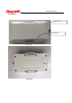
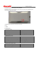
3.3 Definition of connector pins
Pin
Name
Definition
Initial state
Wire Color
1
VCC
Positive power supply
24V DC
Red
2
GND
Negative power supply
Black
3 IGN_IN Ignition signal input High level Yellow
4
RS232 _TXD
Serial data Transmit
RS232
Blue
5 RS232 _RXD Serial data Receive RS232 Purple
6
1-WIRE
1 BUS
Orange
7
ANALOG_IN1
Analog input 1
High level
Green
8
ANALOG_IN2
Analog input 2
High level
Green yellow
9
DIGITAL_IN1
Digital input 1
Low level
10 DIGITAL_IN2 Digital input 2 Low level
11
DIGITAL_OUT1
Digital output 1
12 DIGITAL_OUT2 Digital output 2