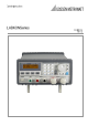
LABKON Series GOSSEN METRAWATT LABKON Series SWITCHING-MODE DC POWER SUPPLY GOSSEN METRAWATT LABKON Series is a series of programmable switching-mode DC power supplies with RS232 and USB (optional) or GPIB (optional) interfaces. The good durability, simple operation, low noise, excellent output accuracy as well as the adjustment from 0V make this series of reliable power supplies the right choice for many applications. It provides flexible and stable DC power for various design and test environments.
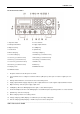
LABKON Series The Front Panel at a Glance 1. AC power switch 2. Sense terminals 3. Earth ground terminal 4. Supply output terminals 5. Output on/off key 6. Left/Right key 7. Control knob 8. Up/Down key 9. Menu setting key 10. Voltage setting key 11. Current setting key 12. Switch key (second menu level) 13. Store key (second menu level) 14. Recall key (second menu level) 15. Error key (second menu level) 16 Local key (second menu level) 17. Secure key (second menu level) 18.
LABKON Series 12. Switch key for second menu level (2nd): Enables the second menu level of other keys. 13. Store key for second menu level (Save): Stores the present operating states in location “0”, “1”, … “9”. 14. Recall key for second menu level (Recall): Recalls a previously stored operating state from location “0”, “1”,…“9”. 15. Error key for second menu level (Error): Checks or reads the error codes. 16.
LABKON Series The Rear Panel at a Glance 1. AC inlet 2. Fuse holder 3. RS232 interface connector 4. GPIB interface connector (optional) 5. Fan outlet An Introduction to this Manual General Information Apart from a general description of your power supply, it provides instructions for checking your power supply, selecting power-line voltage and connecting to AC power. Initial Operation It ensures that the power supply develops its rated outputs and responds to operation from the front panel properly.
LABKON Series Tutorial It describes basic operation of the power supply and gives specific details on the operation and use of GOSSEN METRAWATT LABKON Series power supplies. Specifications It lists the power supply’s basic specifications.
LABKON Series Content An Introduction to this Manual ................................................................................................................................................ 5 General Information ........................................................................................................................................................... 5 Initial Operation ...................................................................................................................
LABKON Series 3.9.2 Over-Voltage .................................................................................................................................................. 23 3.9.3 Over-Temperature .......................................................................................................................................... 23 3.10 The Power Supply Calibration ............................................................................................................................
LABKON Series 5 6 7 4.29 Trigger Commands ............................................................................................................................................. 39 4.30 System-Related Commands ............................................................................................................................... 39 4.31 Calibration Commands ..................................................................................................................................
LABKON Series General Information 1.1 General Information This chapter provides a general description of your power supply. And it also contains instructions relate to initial inspection, selecting the power-line voltage, and connecting your power supply to AC power. 1.2 Safety Considerations This power supply is a safety instrument with a protective earth terminal.
LABKON Series 1.4 Installation 1.5 Initial Inspection When you receive your power supply, please check it for any obvious damage that may have occurred during shipment or resulted from other reasons. If any damage is found, contact the carrier and the Sales Office immediately in order to deal with it in time. Keep the original packing materials in case the power supply has to be returned to GMC-I Messtechnik for repairing in the future.
LABKON Series 2 Initial Operation 2.1 Initial Operation This chapter mainly focuses on three basic tests which should be performed before the operation of the power supply: the preliminary check, the power-on check, and the output check. The preliminary check is to check if the power supply could run correctly.
LABKON Series 2.4 Fuse Replacement 1 Replace the fuse Step 1: Remove the fuse-holder below AC power inlet. Step 2: Replace the fuse with the correct one that meets the requirements. Step 3: Put back the fuse holder. For 115V AC operation, 10AT fuse must be used; For 230V AC operation, 6AT fuse must be used.
LABKON Series 2.5 Power-On Checkout The power-on test includes an automatic self-test that checks the internal microprocessors and a system self-test after the power supply is turned on, which examines the information relate to self-test process shown on the front panel. You will observe the following sequence on the display: 2.6 1. Self-test started It begins with an initial operation immediately after pressing the power switch on.
LABKON Series 2.9 Output Checkout The output checkout is to ensure that the power supply develops its rated outputs and properly responds to various operations. Specific steps are shown as followings: 2.10 Voltage Output Checkout 1. Turn on the power supply. Press the “Power-on” button, and let the power-on check finish. Usually the power supply will go into the power-on / reset state automatically.
LABKON Series 2.11 Current Output Checkout 1. Turn on the power supply. Press “Power-on” button and finish the power-on checkout. Usually the power supply will go into the power-on / reset state automatically and the “OFF” annunciator in the lower right corner of the LCD turns on. Both the voltage value and current value are 0. 2. Connect a short across (+) and (-) output terminals of the supply with an insulated test lead. The 2 sectional area of the shorting stub should be larger than 1.5mm . 3.
LABKON Series 6. Ensure that the current can be adjusted from 0A to the maximum rated value. Adjust the knob until the ampmeter indicates 0A and then until the ampmeter indicates the maximum rated value. If an error has been detected during the output checkout procedures, the ERROR annunciator will turn on. Refer to the related chapters in appendix for more specific error information.
LABKON Series 3 Front Panel Operation 3.1 Front Panel Operation Overview Output on/off Constant Voltage setting Constant Current setting Menu Setting Storing and Recalling Error Messages Display Local/Remote Operation switch Protection Function Power Supply Calibration 3.2 Output on/off The output of the power supply could be switched on or off through this button.
LABKON Series 3.3 Constant Voltage Output Setting Constant voltage output is the most common output of the power supply. The voltage output has a constant value in constant voltage output mode, and it will not change with the load while the current will. The CV annunciator in the lower left corner of the LCD will turn on when the power supply is in constant voltage mode. 1. Connecting a load to the relevant output terminals Turn off the power supply. Connect the load to the relevant output terminals.
LABKON Series 5. Enabling the outputs Press the “Output on/off” key to enable the outputs. “CV” is displayed in the lower right corner of the display. 6. Verifying that the power supply is in the constant voltage mode When you operate the power supply in the constant voltage (CV) mode, if “CC” is displayed in the lower left corner of the display, it indicates that the actual output current value has reached the set value. Therefore please choose a higher current limit value. 3.
LABKON Series 2). Using “Left/Right” keys, knob and “Enter” key to enter: ① Press “Iset” to enter into current setting state. ② Press “Left/Right” keys to move the blinking digit to the corresponding digit of the value. ③ Increase or decrease the relevant value by turning the knob clockwise or counter clockwise, then use “Left/Right” keys to move to the next digit to modify. ④ Press “Enter” key to confirm the current setting value. 5.
LABKON Series Flow Control: *On USB Interface GPIB Interface Off Flow Control: *On Off None Selecting USB GPIB Address: GPIB Address: 5 Address Value Notes: Except the parameters about knob, key sound and interface configuration, other parameters in the main menu will not be saved when the power supply is switched off. If you would like to store relevant parameters, please press “2nd” + “Save” keys or make use of *sav command. 3.
LABKON Series 3.7 Error Messages Display If some error has been detected, “err” annunciator will be lit. Then you can read the error messages through front panel operation with following steps: 1 Press “2nd” + “Error” keys and the display will show the error messages. Example 1: if there is a wrong command, “err” annunciator will turn on. Then check the error messages with following steps: Step Operational Details 1 Press “2nd” +“Error” keys and the display will show the error messages.
LABKON Series 3.10 The Power Supply Calibration Because various factors may cause the reduction of the power supply’s output precision after it has been used for a period of time, the user should calibrate the power supply’s output to make the output return to the previous precision. But it is suggested that the power should not be calibrated frequently. This section mainly introduces how to unsecure the power supply and the detailed procedures of manual calibration. 3.
LABKON Series 3.12 CV Mode Calibration In this mode, three voltage points: 0.5 V, 22 V, 34.5 V (take LABKON P500 35 V / 14.5 A, K148A as example) should be calibrated. A complete overview of calibration checkpoints for all LABKON models is listed on page 57 of this manual. 3.12.1 Wiring 3.12.2 0.5 V Calibration Press “Enter” key, you will see the following figure in the display: Enter the value you read from the multimeter, which is retained to four decimal places.
LABKON Series 3.12.4 4.5 V Calibration Press “Enter” key to verify and then the display will show as follows: Enter the value you read from the multimeter, which is retained to four decimal places. If necessary, press “Clear” key to remove the wrong input value of current digit. Then press “Enter” key to confirm and exit to calibration menu. Now, voltage calibration is completed. 3.13 CC Mode Calibration In this mode, three current points: 0.5 A, 6 A, 9 A (take LABKON P500 35 V/14.
LABKON Series 3.13.3 6 A Calibration Press “Enter” key to verify and then you will see the following: Enter the value you read from the multimeter, which is retained to four decimal places. If necessary, press the “Clear” key to remove the wrong input value of present digit. Then press the “Enter” key to confirm. 3.13.4 9 A Calibration Press “Enter” key to verify and then the display will show as follows: Enter the value you read from the multimeter, which is retained to four decimal places.
LABKON Series 4 Remote Interface Reference 4.1 Remote Interface Reference A detailed description of how to use the remote interface will be given in this chapter, which includes how to program the power supply through the remote interface, the commands format and matters need attention.
LABKON Series 4.3 An Introduction to the SCPI Language SCPI (Standard Commands for Programmable Instruments) is an ASCII-based instrument command language designed for test and measurement instruments. The detailed techniques used to program the power supply over the remote interface are introduced in the following sections. SCPI commands are based on a hierarchical structure, also known as a tree system.
LABKON Series 4.4 Command Format Used in This Manual The format used to show commands in this manual is shown below: CURRent {|MINimum|MAXimum} The command syntax shows that most commands are the mixture of capital and lower case letters. The capital letters indicate the abbreviated spelling for the command. For shorter program lines, send the abbreviated form. For better program readability, send the long form.
LABKON Series 4.6 Using the MIN and MAX Parameters You can substitute MINimum or MAXimum for the parameter of many commands. For example, consider the following command: CURRent {|MIN|MAX} Instead of selecting a specific current, you can substitute MINimum to set the current to its minimum value or MAXimum to set the current to its maximum value. 4.7 Querying Parameter Settings You can query the value of most parameters by adding a question mark (?) to the command.
LABKON Series 4.
LABKON Series 4.12 System-Related Commands DISPlay[:WINDow] [:STATe] {OFF|ON} [:STATe]? :TEXT[:DATA] :TEXT[:DATA]? :TEXT:CLEar SYSTem :BEEPer[:IMMediate] :ERRor? :VERSion? *IDN? *RST *TST? *SAV {1|2|3} *RCL {1|2|3} 4.
LABKON Series SYSTem:ERRor? *CLS *ESE *ESE? *ESR? *OPC *OPC? *PSC {0|1} *PSC? *SRE *SRE? *STB? *WAI 4.15 RS232 Interface Commands SYSTem :LOCal :REMote :RWLock 4.16 Simplified Programming Overview This chapter gives an overview of the basic commands used to program the power supply over the remote interface. Some of them are the SCPI-confirmed commands, and some are the device-specific commands.
LABKON Series 4.18 Using the Low-Level Commands The main feature of the low-level commands is to provide you with more flexibility to change or query the individual parameters than the APPLy command. Give the following example to illustrate how to use the low-level commands to set the supply to an output of 5.0V rated at 4.0A: VOLT 3.3 CURR 2.
LABKON Series For example: APPLY 5.0,2.5 Set the supply to an output of 5.0V rated at 2.5A Executing the low-level commands has the same effect as this command. Please refer to the last section. APPLy? This command queries and returns the power supply’s present voltage and current values for each output. For example: APPLy? 4.21 Query and return the voltage and the current set values of the power supply.
LABKON Series 4.24 Output Setting Commands [SOURce:]CURRent[:LEVel][:IMMediate][:AMPLitude] {[MIN|MAX} This command directly programs the immediate output current level of the output selected with the INST command. [SOURce:]CURRent[:LEVel][:IMMediate][:AMPLitude]? [MIN|MAX] This command checks and returns the immediate current value at the present output terminals of the power supply or the maximum and minimum programmable current levels of the selected output.
LABKON Series [SOURce:]VOLTage[:LEVel]:TRIGgered[:AMPLitude] {[MIN|MAX} This command programs the pending triggered voltage level of the power supply, which is a stored value and transferred to the output terminals when a trigger occurs. A pending triggered level is not affected by subsequent VOLTage commands. [SOURce:]VOLTage[:LEVel]:TRIGgered[:AMPLitude]? [MIN|MAX] This query checks and returns the presently programmed triggered voltage level.
LABKON Series 4.29 Trigger Commands INITiate[:IMMediate] This command causes the trigger system to initiate. This command initiates the trigger subsystem when the trigger source is bus and completes one full trigger cycle when the trigger source is the internal immediate. TRIGger[:SEQuence]:DELay{| MINimum | MAXimum} This command sets the time delay between the detection of an event on the specified trigger source and the start of any corresponding trigger action on the power supply output.
LABKON Series SYSTem:ERRor? This command queries the power supply’s error queue. When “ERROR” annunciator in the front panel turns on, one or more command syntax or hardware errors have been detected. At present, if this command is sent to the power supply through remote interface, the power supply can return corresponding error messages. Up to 20 errors can be stored in the error queue. SYSTem:VERSion? This command queries the power supply to determine the present SCPI version.
LABKON Series *SAV { 0| 2 | ……|9 } This command stores the present state of the power supply, which can store 10 sets of operating states from 0 to 9. The state storage features in saving the states or values of INST[:SEL], VOLT[:IMM], CURR[:IMM], OUTP[:STAT], OUTP:TRAC, TRIG:SOUR and TRIG: DEL. *RCL { 0| 2 | ……|9 } This command recalls a previously stored state. To recall a state, you must store it in advance.
LABKON Series 4.32 RS232 Interface Commands SYSTem:LOCal This command makes the power supply switch to local mode from remote mode. All keys on the front panel are fully functional. The “REM” annunciator on the display is off. SYSTem:REMote This command places the power supply in the remote mode. All keys on the front panel, except the “Local” key, are disabled. The “REM” annunciator on the display is on. SYSTem:RWLock This command places the power supply in the remote mode.
LABKON Series QUEStionable Status Event Registers Enable Registers VOLTage 0 CURRent 1 Not used Not used TEMPerature Output Buffer 4 Not used Not used “OR” Not used Not used OVERvoltage 9 Not used Not used Not used Not used Not used Status Byte Not used Event Registers STAT:QUES? STAT:QUES:ENAB STAT:QUES:ENAB? Enable Registers Not used Not used Standard Event Event Registers Operation Complete OPC Not used Enable Registers 0 QYE 2 Device Depenent Error DDE Execution Error
LABKON Series Bit Definitions - Questionable Status Register Bit Decimal Value Definition 0 (Voltage) 1 The power supply is in constant voltage mode. 1 (Current) 2 The power supply is in constant voltage mode. 2-3 (Not used) 0 Always set to 0. 4 (Over-temperature) 16 The fan has a fault condition. 5-8 (Not used) 0 Always set to 0. 9 (Over Voltage) 512 10-15 (Not used) 0 The power supply is in over-voltage state. Always set to 0.
LABKON Series The standard event register is cleared when: 1. You execute the *CLS (clear status) command. 2. You query the event register using the *ESR? (Event Status register) command. For example, if 28 (4 + 8 + 16) is returned when you query the status of the standard event register, it is certain that QYE, DDE, and EXE conditions have occurred. The standard event enable register is cleared when: 1. You execute the *ESE 0 command. 2.
LABKON Series 4.39 Status Reporting Commands SYSTem:ERRor? This query command reads one error from the error queue. When the front-panel ERROR annunciator turns on, one or more command syntax or hardware errors have been detected. A record of up to 20 errors can be stored in the power supply’s error queue. Additional errors will not be stored. 1. Errors are stored and retrieved in first-in-first-out (FIFO) order. The first error returned is the first error that was stored.
LABKON Series *SRE? This command queries the status byte enable register. The power supply returns a decimal value which corresponds to the binary-weighted sum of all bits set in the register. *STB? This command queries the status byte summary register. The *STB? command is similar to a serial poll but it is processed like any other instrument command. The *STB? command returns the same result as a serial poll but the “Request Service” bit (bit 6) is not cleared if a serial poll has occurred.
LABKON Series STATus :QUEStionable[:EVENt]? :QUEStionable:ENABle :QUEStionable:ENABle? :QUEStionable:ENABle SYSTem :BEEPer[:IMMediate] :ERRor? :VERSion TRIGger [:SEQuence]:DELay {|MIN|MAX} [:SEQuence]:DELay? [:SEQuence]:SOURce{BUS|IMM} [:SEQuence]:SOURce? INITiate[:IMMediate] 4.42 Device-Specific Commands The following commands are specific to the GOSSEN METRAWATT LABKON Series power supply.
LABKON Series MEASure [:SCALar]:CURRent [:DC]? [:SCALar]:VOLTage[:DC]? [:SCALar]:TEMPerature? [SOURce:] CURRent[:LEVel]:LIMit[:AMPLitude] {|MIN|MAX|DEF} CURRent[:LEVel]:LIMit[:AMPLitude]? {MIN|MAX|DEF} VOLTage[:LEVel]:LIMit[:AMPLitude] {|MIN|MAX|DEF} VOLTage[:LEVel]:LIMit[:AMPLitude]? {MIN|MAX|DEF} SYSTem :LOCal :REMote :RWLock _________________________________________________________________________________________________ GMC-I Messtechnik GmbH 49
LABKON Series 5 Tutorial 5.1 Tutorial The GOSSEN METRAWATT LABKON Series is a high performance instrument capable of delivering clean DC power. But to take full advantage of the performance characteristics designed into the power supply, certain basic precautions must be observed when it is connected for use on the lab bench or as a controlled power supply. This chapter gives specific details on the operation of the GOSSEN METRAWATT LABKON Series power supply. 5.
LABKON Series When the load RL is less than RC, the output current will dominate since the voltage will be less than the set voltage. The power supply is said to be in constant-current mode. The load at point B has a relatively low resistance, the output voltage is less than the voltage setting, and the output current is at the current setting. The supply is in constant-current (CC) mode and the voltage setting acts as a voltage limit. 5.
LABKON Series 5.6 Connecting the Load 5.7 Output Isolation The output of the power supply is isolated from earth ground and the power supply can be connected to the ground with the earth ground terminal when needed. Any output terminal can be grounded, and an external voltage source may be connected between any terminal output and ground. However, output terminals must be kept within ±240 V DC of ground. An earth ground terminal is provided on the front panel for convenience. 5.
LABKON Series 5.9 Considerations During the operation of the power supply, various problems may occur because of the difference in connected loads, which will be introduced as follow respectively. 5.10 Capacitive Load In most cases, the power supply will be stable for capacitive loads of any size. Loads with large capacitor may cause ringing in the power supply’s transient response. It is possible that certain combinations of loads will result in output instability.
LABKON Series 5.12 Pulse Load In some applications the load current varies within a large range. The constant current circuit limits the output current. Some peak loading exceeding the current limit can be obtained from the output capacitor. To stay within the specifications for the output, the current limit should be set greater than the peak current expected or the supply may go into CC mode or unregulated mode. 5.
LABKON Series 6 Specifications 6.1 Performance Specifications LABKON P500 35 V / 14.5 A LABKON P500 80 V / 6.5 A LABKON P500 120 V / 4.2 A LABKON P800 35 V / 22.5 A LABKON P800 80 V / 10 A LABKON P800 120 V / 6.5 A Output Ratings Voltage 0 ~ 35 V 0 ~ 80 V 0 ~ 120 V 0 ~ 35 V 0 ~ 80 V 0 ~ 120 V Current 0 ~ 14.5 A 0 ~ 6.5 A 0 ~ 4.2 A 0 ~ 22.5 A 0 ~ 10 A 0 ~ 6.
LABKON Series Readback Resolution Voltage 1 mV 1 mV 2 mV 1 mV 1 mV 2 mV Current 1 mA 1 mA 1 mA 1 mA 1 mA 1 mA 1 mV 2 mV 1 mV (@ 0 … 99.999 V) 10 mV (@ 100 … 120 V) 1 mA 1 mA 1 mA Meter Resolution Voltage 1 mV 1 mV 1 mV (@ 0 … 99.999 V) 10 mV (@ 100 … 120 V) Current 1 mA 1 mA 1 mA 6.2 Transient Response Time Less than 1ms for output to recover to within 100 mV following a change in output current from full load to half load or vice versa 6.
LABKON Series Stability, ±(% of output + offset) Following a 30-minute warm-up, the change occurs in output within 8 hours under constant load, line, and ambient temperature. LABKON P500 LABKON P500 LABKON P500 LABKON P800 LABKON P800 LABKON P800 35 V / 14.5 A 80 V / 6.5 A 120 V / 4.2 A 35 V / 22.5 A 80 V / 10 A 120 V / 6.5 A Voltage 0.02 % + 2 mV 0.02 % + 3 mV 0.02 % + 4 mV 0.02 % + 2 mV 0.02 % + 3 mV 0.02 % + 4 mV Current 0.02 % + 6 mA 0.02 % + 3 mA 0.02 % +2 mA 0.2 % + 6 mA 0.
LABKON Series AC Input Ratings LABKON P500 AC 100 V - 240 V 47 Hz ~ 63 Hz LABKON P800 750 VA max AC 180 V - 265 V 47 Hz ~ 63 Hz 1050 VA max Operating Temperature 0 ~ 40° C 0 ~ 80 % RH Cooling Fan Cooling Programming Language SCPI (Standard Commands for Programmable Instruments) Recommended Calibration Interval 1 year Net Weight 5.
LABKON Series 7 APPENDIX Error Messages 7.1 Error Messages When the front-panel ERROR annunciator turns on, and the power supply generates a short beep, one or more command syntax or hardware errors have been detected. A record of up to 20 errors is stored in the power supply’s memory. Errors are stored and retrieved in first-in-first-out (FIFO) order. The first error returned is the first error that was stored.
LABKON Series -109 Missing parameter Fewer parameters were received than expected for the command. You omitted one or more parameters that are required for this command. Example: APPL -112 Program mnemonic too long A command header was received which contained more than the maximum 12 characters allowed. -113 Undefined header A command was received that is not valid for this power supply. You may have misspelled the command or it may not be a valid command.
LABKON Series -224 Illegal parameter value A discrete parameter was received which was not a valid choice for the command. You may have used an invalid parameter choice. Example: DISP:STAT ABC (ABC is not a valid choice). -350 Too many errors The error queue is full because more than 20 errors have occurred. No additional errors are stored until you remove errors from the queue. The error queue is cleared when power has been off, or after a *CLS (clear status) command has been executed.
LABKON Series 7.4 Calibration Errors Code Explanation 702 Cal secured The calibration is secured. 703 Invalid secure code An invalid calibration security code was received when attempting to unsecure or secure the power supply. You must use the same security code to unsecure the power supply as what was used to secure it, and vice versa. The security code may contain up to 12 alphanumeric characters. 704 Secure code too long A security code was received which contained more than 12 characters.
LABKON Series Product Support If required please contact: GMC-I Messtechnik GmbH Product Support Hotline Phone +49 911 8602-0 Fax +49 911 8602-709 E-Mail support@gossenmetrawatt.com Service Center Repair and Replacement Parts Service Calibration Center and Rental Instrument Service When you need service, please contact: GMC-I Service GmbH Service Center Thomas-Mann-Strasse 20 90471 Nürnberg • Germany Phone +49 911 817718-0 Fax +49 911 817718-253 E-Mail service@gossenmetrawatt.com www.
________________________________________________________________________________________________ Edited in Germany • Subject to change without notice • A pdf version is available on the Internet GMC-I Messtechnik GmbH Südwestpark 15 90449 Nürnberg• Germany Phone +49 911 8602-111 Fax +49 911 8602-777 E-mail info@gossenmetrawatt.com www.gossenmetrawatt.