Operating Instructions METRATESTER 5+ Tester for DIN VDE 0701-0702 3-348-580-15 28/9.
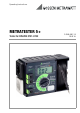
(8) (9) (10) (13) (11) (12) (4) (2) (7) (3a) (6) (5) (1) (3) (1) Mains plug (take-up spool at back of housing for mains cable) (2) Signal lamp PE for testing the mains protective conductor (3) Alligator clips for attachment to the test probe (3a) (3a) Test probe (4) Contacting surface for contact finger (5) Measuring function selector switch RSL Protective Conductor Resistance RISO Insulation Resistance IEA Equivalent Leakage Current IA Contact or Leakage Current (for confirmation of absence of volta
Display Residual Current Secondary Current IDiff mA IDiff mA INetz A UNetz V INetz A Mains Voltage Indication of Limit Values RISO <0.5 MΩ <2.0 RSL >0.3 Ω >1.0 IEA >7.0 mA IA >0.25 mA >0.5 Insulation Resistance PE Resistance Equivalent Leakage Current Leakage Current/ Contact Current Display text subject to change without notice.
Contents Page 1 Safety Features and Precautions ..................................................................................5 2 Applications ...................................................................................................................6 3 Operating and Display Elements ...................................................................................6 3.1 Error and Limit Value Messages ......................................................................................
1 Safety Features and Precautions The tester is manufactured and tested in accordance with the following standards: IEC/EN 61010-1/VDE 0411-1 Safety regulations for electrical measuring, control, regulating and laboratory devices – general requirements and DIN VDE 0404-1/-2: Testing and measuring equipment for checking the electric safety of electric devices; Part 1: general requirements, and Part 2: Testing equipment for tests after repair, change or in case of repeat tests When used for its intended pur
2 Applications The tester is intended for the testing and measurement of repaired or modified electrical devices in accordance with DIN VDE 0701-702. These regulations require the measurement of protective conductor resistance, insulation resistance and equivalent leakage current for repaired or modified electrical devices, as well as testing for the absence of voltage at exposed, conductive parts for data processing systems and office machines.
(8) Test Socket The DUT is connected to the test socket for the measurement of protective conductor resistance, insulation resistance and equivalent leakage current in accordance with DIN VDE 0701-0702, if the DUT is equipped with a mains plug. (9) Connector Jack/Terminal for DUT Phase Conductors This terminal is wired in parallel to the two short-circuited phase conductor terminals at the test socket (8).
3.1 Error and Limit Value Messages Error Message Condition PE Signal Lamp Protective conductor potential, at mains UB > 100 V If contact surface is contacted The following limit values are indicated Measurement Error Condition per Standard Test Instrument Indicates When Limit Values Are Exceeded Red Error Lamp Continuously Lit Limit Values are Displayed Continuous Acoustic Signal (Beeper) RSL > 0.3 Ω 1) • > 0.3 Ω — RSL > 1 Ω 2) • >1Ω • Heating RISO < 0.3 MΩ • < 0.
4 Mains Connection 4.1 Connecting the Tester ➭ Connect the tester to the 230 V mains with the mains plug (1). If no earthing contact socket is available, or if only a three-phase socket is available, connection of the phase conductors, the neutral conductor and the PE conductor can be accomplished with the help of the adapter socket. It includes 3 permanently connected cables and is included with the KS 13 accessory cable set.
4.2 Testing Protective Conductor Potential ➭ Bring the contact finger into contact with the contacting surface (4) and, at the same time, with a grounded object (e.g. a water pipe). The PE signal lamp (2) must not light up! Potential between the mains plug protective conductor (1) and the contacting surface (4) is then ≤ 100 V. Note! The PE signal lamp (2) does not light up, if no mains voltage is present between L and N at the mains plug (1), or if L and PE are reversed at the mains connection.
4.4 Connecting the Device Under Test to the Test Instrument The DUT must be connected to the test socket (8), or to the jacks or terminals (9 and 10) which are connected in parallel to the test socket for the measurement of protective conductor resistance, insulation resistance and equivalent leakage current. Terminal (9) is connected to the short-circuited phase conductor jacks at the test socket (8), and terminal (10) is connected to the earthing contact at the test socket (8).
4.5 General Measuring Procedures Line voltage must lie within the allowable range of 207 to 253 V for all of the following measurements. This assures that the accuracy of displayed measured values corresponds with the values specified under “Technical Data” (chapter 7, page 23). Line voltage can be measured by setting the measuring function selector switch to the “UNetz 250 V” position (see chapter 4.3, page 10).
5 Testing Devices per DIN VDE 0701-0702 The limit values specified in the following chapters correspond to current revision levels of official standards at the time of going to print. Please note that normative legislation is continuously updated to meet the safety requirements necessitated by changing market situations, and that the listed limit values are thus subject to change. Please contact our update service department in order to adapt test instruments to new standards. 5.
5.2 Visual Inspection Visual inspection is performed prior to measurements with the test instrument. Visual inspection includes: • damage to connector cables; • insulation damage; • selection and application of conductors and plugs for their intended use; • condition of mains plug, of connection terminals and wires; • defects of bending protection; • defects of connector cable strain relief; • condition of fastenings, of conductor fixings, of the fuse holder which is accessible to the user, etc.
Maximum Allowable Protective Conductor Resistance Values Depending upon Cable Length Length to [m] 5 12. 5 20 27.5 35 42.5 50 more than 50 Max. resistance [Ω] 0.3 0.4 0.5 0.6 0.7 0.8 0.9 1.0 Under no circumstances may a value of 1 Ω be exceeded. The table is also valid for cable reels and extension cables.
5.4 Measuring Insulation Resistance This measurement may only be performed if the device under test has successfully completed protective conductor resistance testing. If the DUT is equipped with all-pole electrical switches, e.g. undervoltage releases or relays, this test only covers the supply conductor. The device cannot be switched on without being connected to the mains, consequently, it cannot be subjected to an effective insulation test.
Device Type Safety class I devices Safety class I devices with heating elements Safety class II devices Safety class III devices and battery powered devices 1) Limit Value 1 MΩ 0.3 MΩ 1) 2.0 MΩ 1000 Ω/V or 250 kΩ Minimum Display Value 1.15 MΩ 0.38 MΩ 2.25 MΩ Leakage current measurement must be performed if the applicable limit value is fallen short of. Note: „OL“ means measured value > 20 MΩ. ! Attention! If a value of 0.
5.5.1 Measuring Equivalent Leakage Current ! ➭ Attention! Do not touch the instrument’s terminal contacts during equivalent leakage current measurements! Connect the DUT as shown in the followig picture. To test socket IEA ➭ ➭ ➭ Set the measuring function selector switch to the “IEA 20 mA” position. Switch all DUT functions on and make sure, for example, that all contacts for temperature sensitive switches and the like are closed. Read the measured value in “mA” from the LCD.
Frequency response is taken into consideration in accordance with the graph to the right during leakage current measurement. Relative Quantity (dB): 20 log U(f) U(f=10) 5.6 Measuring Contact Current Contact current measurement can be performed instead of insulation resistance measurement for class II devices, or for class I devices with exposed conductive parts which are not connected to the protective conductor.
5.6.2 Measuring Residual Current ! ➭ Attention! The protective conductor test must first be performed and passed. Connect the DUT as shown in the followig picture.. To exposed metal parts To the mains outlet IDiff KS17-4 ➭ ➭ ➭ ➭ ➭ Connect the cable with the test probe to the “2 mA” jack. Set the measuring function selector switch to the “IDiff 20 mA” position. Start up the device under test. Contact all exposed metal parts at the device under test with the test probe.
5.6.3 Direct Method The DUT can remain connected to the mains or to the mains outlet for this test. When testing in accordance with DIN VDE 0701-0702, DUTs with external connections such as data cables etc. can be tested within their entire configuration at the installation site. Note! An RCCB may be tripped if measurement is performed at a defective device! ➭ Connect the DUT as shown in the following picture.
6 Measuring Load Current from the Mains Outlet To the mains outlet INetz ! ➭ ➭ ➭ ➭ Connect the earthing contact plug from the device under test to the mains outlet (7). Set the measuring function selector switch to the “INetz 16 A” position. Switch the device under test on. Read the measured value in “A” from the LCD (11).
7 Technical Data Meas. Quantity Measuring Range Resolution UNO-LOAD Ri PE Resistance 0 ... 19.99 Ω 10 mΩ < 20 V − — Insulation Resistance 0,05 ... 19.99 MΩ 10 kΩ 600 V − approx. 100 kΩ < 10 mA > 1 mA Equivalent Leak. Current 0 ... 19.99 mA ∼ 10 μA 28 V ∼ 2 kΩ < 20 mA — Confirmation of absence of voltage with current measurement (contact or leakage current) 0 … 1.999 mA ∼ 1 μA Residual Current 0.01 … 19.99 mA ~ 10 μA IK IN > 200 mA 2 kΩ Operational Measurements Meas.
Influence Variables and Errors Influence Variable/ Sphere of Influence Designation Influence Errors per ± ... % of measured value DIN VDE 0404 Change in position E1 — Change in supply voltage to the test device E2 2.5 Temperature fluctuation Indicated influence errors per 10 K temperature change: 0 … 21 °C and 25 … 40 °C E3 Current at device under test E4 2.5 Low frequency magnetic fields E5 2.5 DUT impedance E6 2.5 Capacitance during insulation measurement E7 1 with PE resistance 0.
Electrical Safety Protection Class Nom. Mains Voltage Test Voltage II 230 V Mains + PE (mains) + 2 mA socket for testing for the absence of voltage at test socket, connector jacks for phase and protective conductors and gripper clip: 3 kV∼ mains to PE (mains) + 2 mA socket: 1.5 kV∼ Measurement Category II Pollution degree 2 Safety Cut-Off when device overheats Electromagnetic Compatibility EMV Product standards EN 61326-1:2006 class B EN 61326-1:2006 Ambient Conditions Operation Storage Atmosph.
8 Maintenance – Calibration Maintenance Housing No special maintenance is required. Keep outside surfaces clean and dry. Use a slightly dampened cloth for cleaning. Avoid the use of solvents, cleansers or abrasives. Recalibration The respective measuring task and the stress to which your measuring instrument is subjected affect the aging of the components and may result in deviations from the guaranteed accuracy.
9 Repair and Replacement Parts Service Calibration Center* and Rental Instrument Service If required please contact: GMC-I Service GmbH Service-Center Thomas-Mann-Strasse 20 90471 Nürnberg, Germany Phone +49 911 817718-0 Fax +49 911 817718-253 E-Mail service@gossenmetrawatt.com www.gmci-service.com This address is only valid in Germany. Please contact our representatives or subsidiaries for service in other countries.
10 Product Support If required please contact: GMC-I Messtechnik GmbH Product Support Hotline Phone +49 911 8602-0 Fax +49 911 8602-709 E-Mail support@gossenmetrawatt.com Edited in Germany • Subject to change without notice • A pdf version is available on the internet GMC-I Messtechnik GmbH Südwestpark 15 90449 Nürnberg • Germany Phone +49 911 8602-111 Fax +49 911 8602-777 E-Mail info@gossenmetrawatt.com www.gossenmetrawatt.