
Instructions


GMC-I Messtechnik GmbH 19
5.6 Measuring Contact Current
Contact current measurement can be performed instead of insulation resistance measure-
ment for class II devices, or for class I devices with exposed conductive parts which are not
connected to the protective conductor.
• Measuring Equivalent Leakage Current
• Measuring Residual Current
•Direct Method
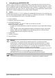
Frequency response is taken into
consideration in accordance with the graph
to the right during leakage current measure-
ment.
Note!
Please note that the current in the protective conductor is also measured both in the
case of equivalent leakage current and in the case of differential current measure-
ment.
Note!
The following schematic diagrams refer to DUTs with a mains plug. See also
chapter 4.4
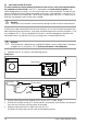
5.6.1 Measuring Equivalent Leakage Current
Attention!
!
Do not touch the instrument’s terminal contacts during equivalent leakage current measurements!
➭ Connect the DUT as shown in the following picture.
➭ Connect the cable with the test probe to the “SL” jack.
➭ Set the measuring function selector switch to the “I
EA
20 mA” position.
➭ Switch all DUT functions on and make sure, for example, that all contacts for tempera-
ture sensitive switches and the like are closed.
➭ Contact all exposed metal parts at the device under test with the test probe.
➭ Read the measured value in “mA” from the LCD.
This value may not exceed 0.5 mA
10 10
2
10
3
10
4
10
5
10
6
+20
0
–20
–40
–60
Frequency (f) in Hz
Relative Quantity (dB): 20 log
U(f)
U(f=10)
I
EA
To test socket
To exposed metal
parts
KS17-4