Operating Instructions METRALINE DM 41 Digital Multimeter 3-447-024-03 2/2.
9 P$ 2 GMC-I Messtechnik GmbH
Multimeter Operating Elements 1 LCD display 2 Multifunction pushbutton (yellow) 3 Pushbutton for relative value 4 Pushbutton for automatic or manual range selection 5 Hz/% pushbutton for V AC & V DC 6 Pushbutton for Data HOLD function 7 Pushbutton for backlight function (optional) 8 Function selector switch for ON/OFF and measurement function 9 Terminal sockets LCD Display 1 Digital display with indication of decimal point and polarity 2 Display of selected current/voltage type 3 Display for automatic measu
Contents Page 1 Safety Features and Safety Precautions ....................................6 2 Initial Start-Up ............................................................................9 3 Function and Range Selection .................................................10 3.1 3.2 3.3 Measuring Function Selection ..................................................................10 Automatic Measuring Range Selection .....................................................
15 Technical Characteristics ....................................................... 24 16 Maintenance ............................................................................ 30 16.1 16.2 16.3 16.4 Battery ...................................................................................................30 Fuses .....................................................................................................32 Housing ............................................................................
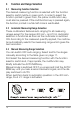
1 Safety Features and Safety Precautions You have selected an instrument which provides you with a high level of safety. The digital multimeter is manufactured in compliance with safety regulations. In case of incorrect use or careless handling, the safety of both user and multimeter is not assured.
• • • • Measurements under moist ambient conditions are not permitted. Do not exceed the permissible overload limits of the measuring ranges. Limit values can be found in the table „Measuring Ranges“ in chapter 15 „Technical Characteristics“. All current ranges are equipped with fuses. The maximum allowable voltage for the measuring current circuit is equal to 600 V~.
Opening of Equipment / Repair The equipment may be opened only by authorized service personnel to ensure the safe and correct operation of the equipment and to keep the warranty valid. Even original spare parts may be installed only by authorized service personnel. In case the equipment was opened by unauthorized personnel, no warranty regarding personal safety, measurement accuracy, conformity with applicable safety measures or any consequential damage is granted by the manufacturer.
2 Initial Start-Up Batteries Please refer to chapter 16.1 on page 30 before initial start-up of your instrument or after a lengthy period of storage. Switching the Multimeter ON Turn the function selector switch from the OFF position to the desired measuring function. All segments of the LCD are activated briefly. A drawing of the LCD can be found on page 2. Note! Electric discharge and high-frequency interference may cause incorrect displays and block the measuring sequence.
3 Function and Range Selection 3.1 Measuring Function Selection The desired measuring function is selected with the function selector switch (white or green print). In order to select the function printed in green color, the yellow multifunction key must also be pressed. If the multifunction key is pressed again, the function printed in white half circle is reactivated. 3.
AUTO / MAN Function brief Manual mode ON: utilized measuring range is fixed Acknowledgement Display 1x 400 mV → 4 V → 40 V → 400 V → 600 V → 400 mV → 4 V → ... V /: 4 V → 40 V→ 400 V → 600 V → 400 mV → ... brief mA : 40 mA → 400 mA → 40 mA ... mA /:40 mA → 400 mA → 40 mA ... Ω: 40 mΩ → 400 mΩ → 4 kΩ → 40 kΩ → 400 kΩ 4 mΩ → 40 mΩ ... V long Acoust.
5 Buzzer The following steps are acknowledged ba an acoustic signal: • Activation or deactivation of the following functions: AUTO/MAN, REL or HOLD, Hz / %, Backlight. • When AC voltage > 750 V is applied, DC voltage > 1000 V, AC/DC mA > 400.0 mA, AC/DC A > 10 A, the buzzer sounds as an overload warning. • Approximately 1 minute before the multimeter is switched Auto Power OFF, the buzzer issues constantly 5 acoustic signals as a sign of warning.
8 Voltage Measurement ➭ Turn the function selector switch to V . ➭ Connect the measurement cable as shown. Terminal „ “ should be grounded and the second measurement cable with a higher potential connected to Terminal „V“.
9 Current Measurement ! Attention! First of all, disconnect the power supply from the measuring circuit and/or the load and discharge any capacitors that might be present. 1 Select function A with the function selector switch for currents > 400 mA or function mA for currents < 400 mA. For measuring currents of an unknown quantity, select the highest measuring range first. 2 Select the function corresponding to the measured quantity by briefly pressing the yellow multifunction key.
• The 10 A current measuring range is protected by a 10 A / 600 V fuse. If a fuse blows, eliminate the cause of the overload before placing the multimeter back into operation! Replacement of the fuses is described in chapter 16.2 on page 32. • • 9 9.1 9.1.1 ! P$ AC Current Measurement with (Clip-on) Current Transformer Transformer Output mA/A Attention! If current transformers are operated with an open circuit on the secondary side, e. g.
The maximum allowable operating voltage at the primary conductor is equal to the nominal voltage of the current transformer. When reading the measured value, consider the transformation ratio of the transformer as well as the additional display error. 9.1.2 Transformer Output mV/A Some transformers have a voltage output (referred to as mV/ A). The secondary output must therefore be connected to the connection sockets „ “ and „V“.
10 Diode Testing and Continuity Measurement 10.1 Diode Testing ! Attention! Verify that the device under test is electrially dead. External voltages would falsify the measurement results! ➭ Set the function selector switch to „ “. ➭ Connect the device under test as shown. Conducting Direction and Short-Circuit The measuring instrument displays the forward voltage in volts. As long as the voltage drop does not exceed the maximum display value of 1.000 V you can test several elements connected in series.
10.2 Continuity Testing ! Attention! Verify that the device under test is electrially dead. External voltages would falsify the measurement results! ➭ Set the function selector switch to „ “. ➭ Press the yellow multifunction key to switch to the continuity measuring range. Display of the symbol is activated. The instrument generates a continuous acoustic signal at a measured resistance of 0 to approx. < 75 Ω. ➭ Connect the device under test as shown below.
11 ! Resistance Measurement Attention! Verify that the device under test is electrically dead. External voltages would falsify the measurement results! ➭ Set the function selector switch to „Ω“. ➭ Connect the device under test as shown below. 9 P$ Zero Adjustment (Relative Mode) In the measurement of resistance, the inherent error of the multimeter and the resistance of leads can be eliminated by zero adjustment. ➭ Short-circuit the leads connected with the multimeter. ➭ Press the REL key.
12 Capacitance Measurement ! Attention! Absolutely verify that the device under test is electrically dead. External voltages would falsify the measurement results! • Set the function selector switch to „F“. Connect the (discharged!) device under test to sockets „ “ and „F“ with measurement cables. Polarized capacitors must be connected to the „ “ socket at the „–“ pole.
Zero Adjustment (Relative Mode) For the measurement of small capacitance values in the 5 nF and 50 nF ranges, the inherent error of the multimeter and the capacitance of the leads can be eliminated by zero adjust ment. ➭ Connect the leads with the multimeter without device under test. ➭ Briefly Press the REL key. The instrument acknowledges zero adjustment with an acoustic signal, and a value close to „00.00“ and REL are displayed on the LCD.
13 Frequency and Duty Cycle Measurement 13.1 Frequency Measurement 1 Set the function selector switch to V~ (V AC) (letter white) and press the Hz/% key, as shown on page 23. The frequency measurement mode is activated. „Hz“ symbol is displayed on the LCD. The digital display is expanded to 9999 digits. Only the auto mode, no manual range is possible. 2 Connections are established in the same way as for voltage measurement.
2 Connections are made the same way as for voltage measurement. 3 Measuring range for duty cycle and maximum allowable voltage can be found in chapter 15 „Technical Characteristics“. 3UHVV +] NH\ 3UHVV +] NH\ 3UHVV +] NH\ 3UHVV +] NH\ 9a 9 14 P$ Temperature Measurement The multimeter allows you to measure temperature with a K-type thermocouple (NiCr-Ni) in the range of –50 °C to +1300 °C. ➭ Set the function selector switch to „°C“. ➭ Connect the sensor as shown below. . W\SH VHQVRU
15 Technical Characteristics Meas. Measuring Resolution FuncRange tion V V A A Ω 24 400.0 mV 4.000 V 40.00 V 400.0 V 600 V 400.0 mV 4.000 V 40.00 V 400.0 V 600 V 100 μV 1 mV 10 mV 100 mV 1V 100 μV 1 mV 10 mV 100 mV 1V 40.00 mA 400.0 mA 10.00 A 1) 40.00 mA 400.0 mA 10.00 A 1) 10 μA 100 μA 10 mA 10 μA 100 μA 10 mA 400.0 Ω 4.000 kΩ 40.00 kΩ 400.0 kΩ 4.000 MΩ 40.00 MΩ 400.0 Ω 100 mΩ 1Ω 10 Ω 100 Ω 1 kΩ 10 kΩ 100 mΩ 1.
Meas. Measuring Resolution FuncRange tion F 5.000 nF 50.00 nF 500.0 nF 5.000 μF 50.00 μF 200.0 μF 1 pF 10 pF 100 pF 1 nF 10 nF 100 nF 10.000 Hz 100.00 Hz 1.0000 kHz 10.000 kHz 100.00 kHz 500.0 kHz 2.0 ... 98.0% 0.001 Hz 0.01 Hz 0.1 Hz 1 Hz 10 Hz 100 Hz 0.1 % Input Impedance V (AC) / V (DC) — Digital display Overload Capacity 3) inherent deviation at referOverload Val- Overence condition ues load +(...% rdg. Dura+...digits) tion 4) 3 + 40 2 + 10 4) 500 V 0.5 + 3 4) 10 DC/AC min 1 + 2 4) rms 1.
Reference Conditions Ambient Temperature Relative Humidity Measuring Magnitude Frequency Measuring Magnitude Waveform Battery Voltage Ambient Conditions Working Temperature Range Storage Temperature Range Relative Humidity Elevation + 23 °C ±2 K 45% ... 55% Sine, 50 Hz Sine 3 V ±0.1 V –10 °C ... + 50 °C –25 °C ... + 70 °C 45 ... 75% up to 2000 m Display LCD display field (58 mm x 31.4 mm) with digital display and display of unit of measure, current type and various special functions.
Influencing Quantities and Effects Influencing Variable Range of Influence Measured Quantity/ Measuring Range V mA/A Temperature Influence Effect ,V , mA/A Ω 0 °C ... +21 °C and +25 °C ... +50 °C F 1 x intrinsic error/K Hz Duty (%) °C Influence Variable Range of Influence (max. resolution) Frequency Intrinsic Error at Ref. ± (... % of rdg + ... D) 4, 40, 400 V 20 Hz ... < 50 Hz > 50 Hz ... 1 kHz 2+3 400 mV, 600 V 20 Hz ... < 50 Hz > 50 Hz ...
Power supply Battery Service life Battery test Fuses Fuse for ranges up to 400 mA Fuse for 10 A range 2 x 1.5 V mignon cell (2x AA-Size) alkaline-manganese cell per IEC LR6. with alkaline-manganese cell: approx. 600 hours Automatic display of „ “ symbol when battery voltage falls below approx. 2.4 V. FF 1.6A/1000V; 6.3 mm x 32 mm; protects all current measuring ranges up to 400 mA FF 10A/600V; 6.
Electrical Safety Installation category Pollution degree High Voltage Test Mechanical Design Protection Dimensions Weight GMC-I Messtechnik GmbH IEC 61010-1-2010 600 V CAT III / 300 V CAT IV 2 3.5 kV ~ (IEC 61010-1-2010) for multimeter: IP50 for terminals: IP20 W x H x D: with holster: 86 mm x 188 mm x 53 mm without holster: 79 mm x 174 mm x 38 mm approx.
16 ! Maintenance Attention! Disconnect the multimeter from the measuring circuit before you open it to replace the battery or the fuse! 16.1 Battery Prior to initial start-up or after storage of multimeter, verify that the batteries inserted in the multimeter do not leak. Repeat this check at regular brief intervals.
! Attention! When inserting the batteries, begin with the positive pole of the battery and fit the negative pole into place afterwards, in order to avoid damage to the contacts of the positive pole. ➭ Tighten the battery compartment cover with the screw. ➭ Dispose of the dead batteries in an environmentally sound fashion.
16.2 Fuses The 10 A fuse interrupts the 10 A current range, and the 1.6 A fuse protects the mA current measuring ranges. All other measuring ranges continue to function. When a fuse blows, eliminate the cause of the overload before putting the instrument back into operation! Replacing the Fuses ➭ Unscrew the cover of the housing base from the top housing. ➭ Remove the defective fuse from the fuse holders, e.g. with the help of a probe and replace it with a new one.
Fuse Testing ➭ Take out the fuse to be tested. ➭ Set the function selector switch to . ➭ Press the yellow function key to select . ➭ Connect the measurement cable with the „V, Ω, , F“ socket. ➭ Measure the resistance of the fuse. ➭ A continuous acoustic signal and the display of approx. 10.2 Ω indicate that the fuse for the mA current range is OK. ➭ A continuous acoustic signal and the display of approx. 0.0 Ω indicate that the fuse for the A current range is OK.
16.4 Returns and Environmentally Sound Disposal The instrument is a category 9 product (monitoring and control instrument) in accordance with ElektroG (German Electrical and Electronic Device Law). This device is subject to the RoHS directive. Furthermore, we make reference to the fact that the current status in this regard can be accessed on the Internet at www.gossenmetrawatt.com by entering the search term WEEE.
17 Product Support If required please contact: GMC-I Messtechnik GmbH Product Support Hotline Phone: +49 911 8602-0 Fax: +49 911 8602-709 E-mail support@gossenmetrawatt.com 18 Repair and Replacement Parts Service Calibration Center* and Rental Instrument Service If required please contact: GMC-I Service GmbH Service Center Beuthener Str. 41 90471 Nürnberg, Germany Phone: +49 911 817718-0 Fax: +49 911 817718-253 E-mail service@gossenmetrawatt.com www.gmci-service.
19 Manufacturer‘s Warranty Digital multimeters of the METRALINE DM series are guaranteed for a period of 3 years after shipment. The manufacturer’s warranty covers materials and workmanship. Damage resulting from use for any other than the intended purpose or operating errors, as well as any and all consequential damages are excluded. Kindly register each device at myGMC after purchase in order to benefit from the 3 year warranty. 20 Registration Register your device at www.gossenmetrawatt.