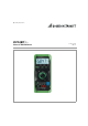
Operating Instructions METRAHIT2+ Universal TRMS Multimeter 3-349-478-03 10/6.
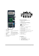
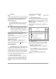
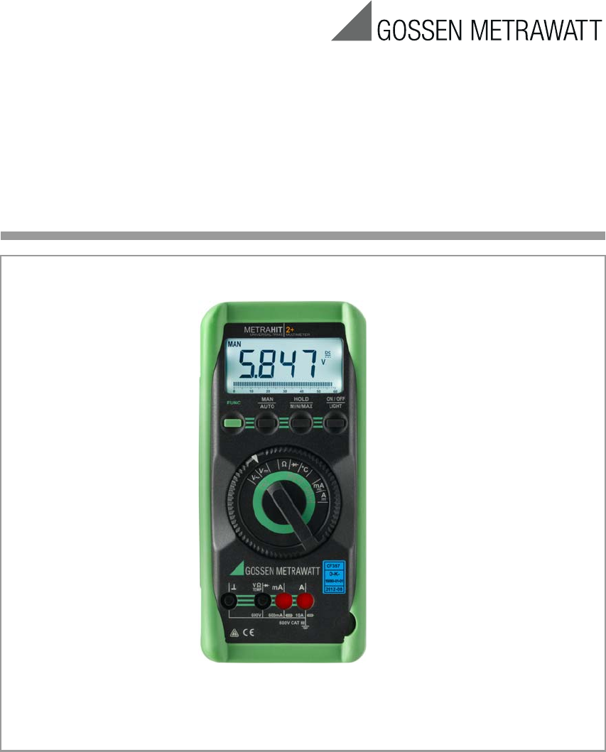
1 3 4 5 6 1 18 7 17 8 16 2 9 15 3 4 14 13 12 11 10 5 6 7 Symbols used in the Digital Display 1 MAN: manual measuring range selection is active 2 MIN/MAX value storage 3 HOLD: display memory, “freeze” measured value 4 Digital display with decimal point and polarity display 5 Diode measurement selected 6 Max.
Table of Contents 16 Repair and Replacement Parts Service, Calibration Center and Rental Instrument Service ... 18 Page 1 Safety Features and Precautions ...............................3 17 Manufacturer‘s Guarantee ....................................... 18 2 Initial Start-Up ............................................................5 18 Product Support ....................................................... 18 3 Selecting Measuring Functions and Measuring Ranges ..............................
• • • • • • Make certain that the measurement cables are in flawless condition, e.g. no damage to insulation, no interruptions in cables or plugs etc. No measurements may be made with this instrument in electrical circuits with corona discharge (high-voltage). Special care is required when measurements are made in HF electrical circuits. Dangerous pulsating voltages may be present. Measurements under moist ambient conditions are not permitted.
2 Initial Start-Up Battery Your instrument is supplied with two 1,5 V AA size batteries in accordance with IEC LR 6, and is ready for operation. Be sure to refer to chapter 13.1 “Battery”, before initial start-up, or after your device has been in storage for a lengthy period of time. Switching the Instrument On ➭ Press the ON / OFF key. Power-up is acknowledged with an acoustic signal. All of the segments at the liquid crystal display (LCD) are illuminated shortly.
3.4 Relative Measurement REL A reference value for relative measurements can be stored to memory with the keys MAN / AUTO and HOLD. The applicable reference or correction value is substracted individually for the respective measuring function as an offset from all subsequent measurements, and remains in memory until deleted, or until the multimeter is switched off. Reference value setting is only possible for the respective manually selected measuring range.
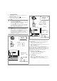
Voltage Measurement ➭ Depending upon the voltage to be measured, set the rotary selector switch to V or V . Connect the measurement cables as shown. The “” connector jack should be grounded. ➭ Note! The 600 mV measuring range can only be selected manually with the MAN / AUTO key. If the measured value exceeds 60 V DC or 40 V AC the symbol appears at the display. An intermittent acoustic signal warns the operator if the measured value exceeds the upper range limit value of 600 V in the 600 V range.
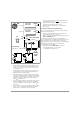
➭ ➭ ➭ ➭ Current Measurement First disconnect supply power from the measuring circuit or the consuming device, and discharge any included capacitors. Select the A range with the rotary selector switch for current greater than 600 mA, or the mA range for current less than 600 mA. Activate the highest measuring range first when measuring current of an unknown magnitude. Select the current type appropriate for the measured quantity by briefly pressing the FUNC key.
00.00 mA ... 60 mA 000.0 ... 600 mA FUNC brief mA DC AC~ mA DC AC~ DC AC~ 1x acoustic signal AC ~ DC Measuring Range: mA: 60 mA 600,0 mA • • connector jacks.The following symbol appears at the digital display in this case: . If a fuse blows, eliminate the cause of overload before placing the instrument back into service! Refer to chapter 13 “Maintenance”, regarding fuse replacement.
8.1 Measuring Alternating Current with (Clip-On) Current Transformers 8.1.1 Transformer Output mA / A ! Attention! If current transformers are operated without being connected at the secondary side (e.g. as a result of defective or missing cables, a blown device fuse or incorrect connection), dangerously high voltages may occur at the connector jacks.
10 ➭ ➭ ➭ Continuity and Diode Testing Make sure that the device under test is voltage-free. Interference voltages distort measurement results! Set the rotary selector switch to . Connect the device under test as shown. 0.000 FUNC brief 030.
11 Temperature Measurement The multimeter provides for the measurement of temperatures within a range of – 50°C to + 400°C with the help of a type K temperature sensor. ➭ Set the rotary selector switch to „°C“. ➭ Connect the sensor to the two accessible jacks. The device indicates the measured temperature in C at the digital display. ➭ Briefly press the FUNC key to switch between C and F.
12 Characteristic Values Meas. Function Measuring Range Resolution V 600 mV 6 V 60 V 600 V 6000 100 V 1 mV 10 mV 100 mV A 60 mA 600 mA 6 A 10 A 10 100 1 10 Input Impedance Intrinsic Error at Max. Resolution under Reference Conditions (... % rdg. + ... d) (... % rdg. + ... d) 5) 10 M // < 40 pF 8.1 M // 50 pF 5.2 M // < 40 pF 4.6 M // 50 pF 5 M // < 40 pF 4.4 M // 50 pF 5 M // < 40 pF 4.4 M // 50 pF Voltage drop at approx. range limit 0.5 + 5 0.5 + 5 0.5 + 5 0.5 + 5 1+5 1.
Influencing Quantities and Influence Error Influencing Measured Quantity / Influence Error 1) Quantity Sphere of Influence Measuring Range (... % rdg. + ... digits) 600 mV 1.0 + 3 6 ... 600 V 0.15 + 1 V 0.4 + 2 60 mA ... 600 mA Temperature 0 C ... +21 C and +25 C... +40 C 0.5 + 1 A 0.75 + 1 0 2) 0.15 + 2 600 0.25 + 2 6 k ... 6 M 0.15 + 1 40 M 1.0 + 1 – 50 ... + 200 C 1K+2 > 30 Hz ... 45 Hz A > 65 Hz ...
Reference Conditions Ambient temperature Relative humidity Measured quantity frequency Measured quantity waveshape Battery voltage + 23 C 2 K 40 % ... 60 % 45 Hz ... 65 Hz sinusoidal 3 V 0.1 V Display LCD panel (65 mm x 30 mm) with analog and digital display including unit of measure, type of current and various special functions Analog: Display LCD scale with pointer Scale length 55 mm for all ranges Scaling 0 ...
13 Maintenance ! Attention! Disconnect the instrument from the measuring circuit before opening to replace batteries or fuses! 13.1 Battery Make sure that no battery leakage has occurred before initial start-up, and after long periods of storage. Continue to inspect the batteries for leakage at short, regular intervals. If battery leakage has occurred, carefully and completely clean the electrolyte from the instrument with a damp cloth, and replace the batteries before using the instrument.
If you use batteries or rechargeable batteries in your instrument or accessories which no longer function properly, they must be duly disposed of in compliance with the applicable national regulations. Batteries or rechargeable batteries may contain harmful substances or heavy metal such as lead (PB), cadmium (CD) or mercury (Hg).
16 Repair and Replacement Parts Service, Calibration Center* and Rental Instrument Service If required please contact: GMC-I Service GmbH Service Center Thomas-Mann-Str. 16-20 90471 Nürnberg • Germany Phone +49 911 817718-0 Fax +49 911 817718-253 e-mail service@gmc-instruments.com www.gmci-service.com This address is only valid in Germany. Please contact our representatives or subsidiaries for service in other countries.