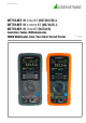
Operating Instructions METRAHITIM XTRA BT (M273A/D/W) & METRAHITIM E-DRIVE BT (M274A/B) & METRAHITIM TECH BT (M272A/B) Insulation Tester, Milliohmmeter, TRMS Multimeter, Inter-Turn Short Circuit Tester 3-447-035-03 8/2.
Scope of Delivery (depending on instrument variant) 1 1 1 1 1 1 1 1 1 Multimeter with rubber holster HC40 hard case (for multimeter and accessories) (Z270K: black or Z270H: orange) Quick-change, rechargeable lithium polymer battery with USB power pack (5 V DC, 2 A) (Z270A or Z270G) Probe (with start/stop and store/send function) (Z270S) (METRAHIT IM XTRA BT and METRAHIT IM E-DRIVE only) Cable set (1 pair of safety measurement cables, red/black, with 4 mm test tips) (GTY362003P0002) Pair of KC4 Kelvin clip
Contents 1 Page Contents Page Safety Instructions ............................................................ 5 8 Measurements.................................................................24 2 Applications....................................................................... 6 2.1 2.2 2.3 2.4 2.5 Intended Use / Use for Intended Purpose .................................... 6 Use for Other than Intended Purpose........................................... 6 Liability and Guarantee ................
12 Accessories..................................................................... 66 12.1 12.2 General .......................................................................................66 Technical Data for Measurement Cables (included with KS17-2 cable set and Z270S probe) ...................66 13 Returns and Environmentally Sound Disposal ................ 66 14 CE Declaration ................................................................ 67 15 Addresses ..................................
1 Safety Instructions Observe this documentation, in particular all included safety information, in order to protect yourself and others from injury, and to prevent damage to the instrument. • • • • • • • • • • • • • • • • • • • • • • • • • Carefully and completely read and adhere to these operating instructions, as well as the instrument’s condensed operating instructions. The respective documents can be found at http://www.gossenmetrawatt.com. Retain these documents for future reference.
2 Applications Please read this important information! 2.1 Intended Use / Use for Intended Purpose The METRAHIT IM XTRA BT is multimeter, milliohmmeter, insulation measuring instrument, coil tester and data logger in one. The METRAHIT IM E-DRIVE BT is a multimeter, milliohmmeter, insulation measuring instrument, coil tester and data logger for hybrid and electric drives. The METRAHIT IM TECH BT is multimeter, milliohmmeter and data logger in one.
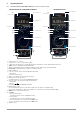
4 Operating Overview 4.1 Connections, Keys, Rotary Switch, Symbols (depending on instrument variant) METRAHIT IM XTRA BT and METRAHIT IM E-DRIVE BT 1 section 5.1 15 METRAHIT IM TECH BT 1 section 5.1 15 section 6.5 section 6.5 2 section 4.2 2 section 4.2 3 section 3.3 14 14 13 12 11 10 9 10 11 12 13 14 15 4 section 7.6 13 4section 7.6 5 12 5 6 section 4.3 6 section 4.3 7 section 4.4 7 section 4.4 8 8 11 9 9 1 2 3 4 5 6 7 8 3 section 3.3 Max.
4.
4.4 Symbols on the Instrument ! Warning concerning a point of danger (attention, observe documentation!) Ground CAT III/IV Measuring category III (1000 V) or IV (600 V) instrument Continuous, doubled or reinforced insulation European conformity marking Fuse (see section 11.2) This instrument may not be disposed of with household trash. Further information regarding the WEEE mark can be accessed on the Internet at www.gossenmetrawatt.com under the search term WEEE (see also section 13).
5 Initial Startup The instrument must first be supplied with power. The instrument is powered by the rechargeable battery pack included in the scope of delivery. The rechargeable battery packis equipped with a patented, contact-protected module socket, which makes replacement possible without interrupting the measuring circuit. Note The optional M27x charger (Z270L) includes primary connectors for Central Europe, the UK, North America and Asia.
Charge level symbols: Battery full Battery OK Battery weak Charge the battery pack as soon as possible. ! Attention! Do not perform any safety-relevant measurements if the “battery low” symbol appears in the battery display. Moreover, compliance with the specified data is no longer assured when the battery is weak. Battery (almost) dead, U < 3.3 V ! 5.
6 System Settings After initial startup, basic system settings have to be selected, for example date and time. System settings can be changed at any time. System settings can be accessed in the General Setup menu. deleted with the help of the BackSp (backspace) key. You can move the blinking cursor in the entry field to the desired position within the word using the < or > softkey in order to add characters, or to delete them with the help of the BackSp softkey.
➭ Select the System parameter with the help of the scroll keys. 6.7 ➭ Switch to the submenu with the help of the scroll key. ➭ Select the Date or Time parameter with the help of the scroll keys. ➭ Acknowledge the selected parameter by pressing the OK key. The entry cursor jumps to a random position in the settings menu. ➭ Select the desired entry position with the scroll keys and change the respective value with the scroll keys. ➭ Acknowledge your change with the OK key.
➭ Acknowledge the selected parameter by pressing the OK key. Old Password appears in the header and the digital keyboard is displayed. ➭ Enter the password via the digital keyboard. ➭ Press the Enter softkey. New Password appears in the header and the digital keyboard is displayed. ➭ Press the Enter softkey without making any entry. Acknowledge Password appears in the header and the digital keyboard is displayed. ➭ Press the Enter softkey again without making any entry. The password is deleted.
➭ Press the MENU key. ➭ Press the General Setup softkey. ➭ Select the System parameter with the help of the scroll keys. ➭ Switch to the submenu with the help of the scroll key. ➭ Select the Default Settings parameter with the help of the scroll keys. ➭ Acknowledge by pressing the OK key. ➭ The following warning appears: “Reset?”. The settings are not reset until you scroll to Yes with the scroll key and acknowledge by pressing OK.
7 Control Functions 7.1 Help The following information can be displayed for switch positions and basic functions after they’ve been selected with the rotary selector switch: • • • • Explanation of the measurement Measuring ranges Wiring diagram QR code link for accessing the operating instructions ➭ Press the MENU key to this end. ESC ➭ Then press the “Help for present measurement” softkey. Comments concerning the measurement are displayed.
7.2 Selecting Measuring Functions and Measuring Ranges 7.3 Zero Offset / Relative Measurements Zero offset or a reference value for relative measurements can be stored to memory depending upon deviation from the zero point: 7.2.1 Automatic Range Selection The multimeter is equipped with auto-ranging for all measuring functions except for temperature measurement, as well as diode and continuity testing. Auto-ranging is active as soon as the instrument is switched on.
7.4 Display (TFT) 7.4.1 Digital Display Measured Value, Unit of Measure, Type of Current, Polarity The measured value with correct decimal and plus or minus sign appears at the digital display. The selected unit of measure and current type are displayed as well. A minus sign appears to the left of the value during the measurement of zero-frequency quantities, if the plus pole of the measured quantity is applied to the “” input.
7.5.
7.6 Measured Value Memory – STORE Function. The following options are available for the storage of measured values: • • • Store at the instrument by pressing the STORE key on the instrument Store at the instrument by pressing the STORE key on the probe (METRAHIT IM XTRA BT and METRAHIT IM E-DRIVE BT only) Store at the PC by triggering the PUSH/PRINT function in the IZYTRONIQ report generating program 7.6.
7.7 Measurement Data Recording The general procedure is described here first, and the following subsections explain the respective parameters and their configuration in detail. ➭ Activate recurrent recording: ➭ Press the MENU key. ➭ Press the General Setup softkey. ➭ Select the Memory menu with the scroll keys. ➭ Switch to the submenu with the help of the scroll key. ➭ Select the Recording Type parameter with the help of the scroll keys.
➭ Memory mode operation can also be exited by switching the multimeter off. This parameter cannot be set during memory mode operation. ➭ Press the MENU key. Setting the Sampling Rate ➭ Press the General Setup softkey. This parameter cannot be set during memory mode operation. ➭ Select the Memory menu with the scroll keys. ➭ Press the MENU key. ➭ Switch to the submenu with the help of the scroll key. ➭ Press the General Setup softkey.
Activating the Trigger Selecting a Group The trigger function cannot be set during memory mode operation. Before starting the respective measurement, select a suitable group from the list you’ve created to which the measured values will be saved. ➭ Press the MENU key. ➭ Press the General Setup softkey. ➭ Select the Memory menu with the scroll keys. ➭ Switch to the submenu with the help of the scroll key. ➭ Select the Trigger parameter with the scroll keys.
8 Measurements 8.1 Enabling Parameter Changes 8.2 If password protection has been set up (see section 6.7), the password has to be entered for each of the following measurements in order to change the parameters: • • Insulation Resistance Measurement – RISO Function (METRAHIT IM XTRA BT and METRAHIT IM E-DRIVE BT only) Caution: High-Voltage! Do not touch the conductive ends of the test probes when the instrument has been activated for the measurement of insulation resistance.
➭ Connect the measurement cables to the accessible M and sockets, using the included probe for connection to the M socket if possible. RISO ➭ Set the rotary switch to “RISO” or “COIL”. ➭ Interference voltage testing (V AC+DC TRMS) is conducted in this switch position. ! Attention! If interference voltage of roughly Uext < 15 V AC or < 25 V DC is detected, visual and acoustic warnings are generated. Measurement is disabled as well.
8.2.2 Performing Insulation Measurement ➭ Don’t read the measurement results until the display has settled in. The high-voltage symbol next to the battery level display blinks during measurement. Auto-ranging is active during insulation resistance measurement. A DATA function which is matched specifically to the insulation measurement can be activated for automatic retention of valid measured values (see section 7.2.1).
Selecting the Type of Measurement 8.3.1.1 Preparing for Measurement MENU RISO Connect COIL TEST ADAPTER and measurement cables COIL U ! 0 V! Pulse Current up to 600 A is Possible! S– A M COIL USurge max 1200 V! W Example with Star Connection m/4 OK Coil / 1-Ph. Motor / 3-Ph. Motor ESC 3 x > Measurement View OK 1-Ph. Motor: AC motor (L1) 3-Ph. Motor: 3-Phase motor (U-V, U-W, V-W) Coil Motor with up to 15 coils (L1 - L15) ➭ Select polarity: unipolar or bipolar (see below).
Test Voltage (Uset = 1000 V) Test voltage for the inter-turn short circuit measurement is permanently set to 1000 V and cannot be changed. ➭ You can delete each measurement in order to repeat it by selecting the desired table row for U-V, U-W or V-W with the or scroll key and pressing the Delete softkey. Connection and Contacting ➭ Make sure that the device under test is voltage-free. Note Interference voltage cannot be detected in combination with the COIL TEST ADAPTER (COIL ADAPTER 50 mH).
In the case of permanent-field motors, inter-turn short circuit measurement is dependent on rotor position. This also applies to squirrel cage motors with large inductances which result in more frequently occurring remanence. In this case, the bipolar setting must be selected for the inter-turn short circuit measurement. First of all, measurement must be performed at each coil with positive polarity. Afterwards, each coil is measured once again with reversed polarity.
8.3.2 Inter-Turn Short Circuit Measurement with the ADAPTER XTRA* In combination with the optional COIL ADAPTER XTRA, inter-turn short circuit measurements with a test voltage of 1000 V are possible within an inductance range of 10 μH to 5 H (100 Hz). Switch set to High: 5 mH to 5 H Low: 10 μH to 50 mH This range corresponds to motors in accordance with DIN standards with power ratings of roughly 0.16 kVA to 80 MVA. Switch set to High: from roughly 0.
Viewing the Automatically Selected Measurement Type and Polarity Mode MENU > Setup for present measurement > Parameters Measurement type: Polarity mode: Press ➭ Make sure that the device under test is voltage-free. Note In combination with the COIL ADAPTER XTRA, interference voltage can only be detected under certain conditions. 3-phase motor (U, V, W) Bipolar ESC Connection and Contacting ➭ Connect the COIL ADAPTER XTRA to the S+ and sockets at the multimeter via the contact protected plug.
Measured Value Display Graphic Graphic representation is used as a standard feature for the measurement view. If the instrument is in the list view, you can switch to the graphic display by pressing the Graphic softkey. Horizontal axis: Coil U-V, U-W, V-W Vertical axis: Time value in μs The currently measured time value for the coil selected at the multimeter is digitally displayed in microseconds to the right of the bar graph.
8.3.2.3 Starting a New Measurement Series / Measuring Routine In order to start a new measurement series, you can: – – – Delete the respectively recorded measurement for each coil as described under “Measured Value Displays”, or Reselect the COIL measuring function with the help of the Func softkey (or by turning the rotary switch) Start a new measurement series by pressing the Restart softkey 8.3.2.
8.4 Absorption Index Measurement – DAR (METRAHIT IM XTRA BT and METRAHIT IM E-DRIVE BT only) The absorption index test is part of the polarization index test (PI). Insulation resistance measurements are placed in relationship to one another after 30 and 60 seconds. Application: faster version of the polarization index test. ➭ Set the rotary switch to “RISO”. RISO COIL ➭ Repeatedly press the Func softkey until the measurement view for DAR appears at the display.
Polarization index testing is recommended for electric machines. This procedure involves expanded testing of insulation resistance RISO. DC measuring voltage from the multimeter is applied to the insulation for a duration of 10 minutes. The measured RISO value is documented after one minute, and after ten minutes. If the insulation is good, the value measured after ten minutes is higher than the value measured after one minute. The relationship between the two measured values is the polarization index.
8.6 ! Voltage Measurement Warning! Be aware of the fact that dangerous voltage spikes are not displayed during measurement with the low-pass filter. Measure voltage without the low-pass filter first, in order to be able to detect any dangerous voltages. Note Rotary selector switch position “RISO” is available for the detection of interference voltage during insulation resistance measurement. Use switch position V , V or V in order to perform precise voltage measurements.
Voltage Comparator for Displaying Dangerous Voltage Voltage Comparator for Displaying Dangerous Voltage The input signal or measuring signal is checked by a voltage comparator for dangerous spikes, because these do not appear at the display when the low-pass filter is used.
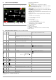
V~ VAC Hz Measuring Ranges: Duty AC: 5.0 ... 98.0% Duty AC Measuring Ranges: MR 3V 30 V S– Hz tE/tP 15 Hz ... 1 kHz, 1 kHz ... 4 kHz, 15 Hz ... 1 kHz, 1 kHz ... 4 kHz, V Temp COIL S+ Func Hz 10 ... 90% 10 ... 90% 5 ... 95% 15 ... 85% m/4 A Duty AC Func RPM AC Func VAC Fil Func Max.
8.6.4 Direct and Pulsating Voltage Measurement, V DC and V (AC+DC) ➭ Set the rotary switch to V or V . VDC ➭ Press the MENU key. V ➭ Press the “Setup for present measurement” softkey. ➭ Make sure that the Clip parameter is set to Off. Otherwise all measured values are displayed in amperes, corrected by the amount resulting from the selected transformation ratio for an interconnected current clamp sensor. V ➭ The display is returned to the measurement view by pressing the ESC key twice.
8.7 Resistance Measurement “” ➭ Disconnect supply power from the electrical circuit of the device to be measured, and discharge all high-voltage capacitors. ➭ Make sure that the device under test is voltage-free. Interference voltages distort measurement results! Refer to section 8.6.4 regarding testing for the absence of voltage with the help of the direct voltage measurement. ➭ Set the rotary switch to “”. ➭ Repeatedly press the Func softkey until the “” measuring function is displayed.
8.8 Capacitance Measurement F ➭ Disconnect supply power from the electrical circuit of the device to be measured and discharge all high-voltage capacitors. ➭ Make sure that the device under test is voltage-free. Capacitors must always be discharged before measurement is performed. Interference voltages distort measurement results! Refer to section 8.6.4 regarding testing for the absence of voltage with the help of the direct voltage measurement. ➭ Set the rotary switch to “” or .
8.9 Temperature Measurement with Resistance Thermometers – Temp RTD Temperature measurement is performed with a Pt100 or Pt1000 resistance thermometer (accessory, not included), which is connected to the voltage input. ➭ Set the rotary switch to “” or “Temp”. ➭ Repeatedly press the Func softkey until the Temp RTD measuring function is displayed. ➭ Select the connected temperature sensor (see settings menu below).
8.10 Temperature Measurement with Thermocouple – Temp TC Temperature measurement is performed with a type K thermocouple (accessory, not included), which is connected to the voltage input. ➭ Set the rotary switch to “” or “Temp”. ➭ Repeatedly press the Func softkey until the Temp TC measuring function is displayed. The reference temperature is measured via an internal reference junction. It’s displayed as TINT, or it can be queried via “General Setup” (see description below).
8.11 Continuity Test 8.12 Diode Testing with Constant Current of 1 mA ➭ Disconnect supply power from the electrical circuit of the device to be measured and discharge all high-voltage capacitors. ➭ Disconnect supply power from the electrical circuit of the device to be measured and discharge all high-voltage capacitors. ➭ Make sure that the device under test is voltage-free. Interference voltages distort measurement results! ➭ Make sure that the device under test is voltage-free.
8.13 Milliohm Measurement – Rlo (2-wire measurement) (METRAHIT IM XTRA BT and METRAHIT IM E-DRIVE only) ➭ Disconnect supply power from the electrical circuit of the device to be measured and discharge all high-voltage capacitors. ! Attention! The device under test must be voltage-free! If interference voltage of Uext > 2 V is detected, visual and acoustic warnings are generated. Measurement is disabled as well. Refer to section 8.6.
8.14 Milliohm Measurement – m/4 (4-wire measurement) 8.14.1 Compensation of Cable Resistance Electrical resistance is a dipole which can generally only be measured using two poles. This is accomplished by directing a measuring current of predetermined magnitude through the device under test and measuring the resultant voltage drop. The respective resistance value is derived from the quotient of these two values.
Measuring Instrument at Remote Location The cable reel and the measuring instrument connected to it (including the part of the Kelvin measuring device connected to the measuring instrument) are located at a distance from the measuring site. Only the second part of the Kelvin measuring device connected to the extension cord is in direct proximity to the inspector. Example: Wind power turbine. 8.14.
8.14.3 Milliohm Measurement with 200 mA or 20 mA DC [m KC4 Kelvin clips and KC27 Kelvin probes (available as accessories) allow for simple, correct connection. The KCV100 accessory cable reel for 4-wire measurement (100 meters) can be used for measurements at large objects (see “Accessories (sensors, plug inserts, adapters, consumable materials)” on page 2). Resistance at the current jacks should amount to < 5 . This measuring method is suitable for resistances with inductances of up to 1 H.
8.15 ! Current Measurement Attention! Set up the measuring circuit in a mechanically secure fashion, and secure it against inadvertent breaks. Select conductor cross-sections and lay out connections such that they do not overheat. A A A DC Note In the case of current greater than 1.1 A, “OL” appears at the display. A DC Measuring Range: A : 10 nA ... 1 A 8.15.
8.15.2 Alternating Current and Frequency Measurement, Direct Connection, – AAC and Hz ➭ First disconnect supply power from the measuring circuit or the power consumer (1), and discharge any capacitors. ➭ Set the rotary switch to A (A ). ➭ Repeatedly press the Func softkey until the desired measuring function is displayed. A A A DC ➭ If necessary, conduct zero balancing for AAC by pressing the Zero softkey (see description below).
8.15.3 Direct and Pulsating Current Measurement with Current Clamp Sensor – ADC und A (AC+DC) V Voltage/Current Transformer Output When a current clamp sensor is connected to the multimeter (V input), all current displays appear with the correct value in accordance with the selected transformation ratio.
8.15.4 Alternating Current Measurement with Current Clamp Sensor – AAC and Hz V~ Voltage/Current Transformer Output When a current clamp sensor is connected to the multimeter (V input), all current displays appear with the correct value in accordance with the selected transformation ratio. The only prerequisite is that the current sensor is equipped with at least one of the below listed transformation ratios, and that the ratio has been previously selected in the following menu (Clip Off).
8.16 Measuring Sequences – Test Sequences If the same sequence of single measurements will be run frequently (one after the other with subsequent report generation), it’s advisable to make use of measuring sequences (also called test sequences). One sequence with up to 10 measurement steps can be created in the METRAHIT IM XTRA and the METRAHIT IM E-DRIVE. The measuring steps can include measuring functions as well as measuring instructions.
➭ Press the Delete softkey. Running a Test Sequence ➭ Acknowledge the security prompt. ➭ The sequence is deleted. Specifying Measured Value Storage for Sequences Measured values can be saved in different ways when running a sequence (see below): • • Automatic: The value is saved by pressing the STORE key and the next sequence step is started automatically. Manual: The value is saved by pressing the STORE key. The next sequence step isn’t started until the OK key is pressed.
Overview of the Meanings of Softkeys and Hard Keys Key Function Softkeys New Create a new test sequence Rename Change the name of the test sequence Ins. text Enter text above the selected line* Ins. Function Insert a measurement step with a measuring function above the selected line Ins.
9 Establishing a Bluetooth® Connection Interface Operation and Software The multimeters are equipped with a Bluetooth® interface by means of which they can establish connection to a PC, a smartphone (Android™) or a tablet (Android™). 9.1 Bluetooth® Establish connection to your PC, smartphone (Android) or tablet (Android) in the usual way for the respective system. Read the documentation included with the device in this regard.
9.2 Software for Receiving and Evaluating Data We recommend METRAHIT IM Data Reader software for your PC. Alternatively, you can retrieve measured values using a terminal program. Data can be conveniently displayed and evaluated on a smartphone (Android) or a tablet (Android) with the METRALOG app. We recommend Sequence Manager PC software for the management of measuring sequences. ! Attention! Always create a backup copy of your measurement data. Any and all liability for loss of data is excluded.
9.2.3 METRALOG App (smartphone and tablet) METRAHIT IM XTRA BT and the METRAHIT IM E-DRIVE BT, none for the METRAHIT IM TECH BT. With Sequence Functions Expert: 16 sequences with up to 63 test steps.
Program Controls The Sequence Manager is only available in English. About Read Sequences Program Workspace Tools Read Out Information Sequences from Connected Progress Bar Instrument Instrument Read from Instrument ➭ Connect the instrument to your PC via Bluetooth® (see section 9.1 on page 56). ➭ Start the program using the usual procedure for your operating system. ➭ Click the Read Sequences from Device button. The Read Sequences from Device dialog appears.
Saving Sequences as a File Test sequences can be saved as a TXT file for use as a backup copy, as well as for subsequent transfer to other instruments (see below). All sequences from the current workspace are always exported. ➭ Click the Export Sequences to File button. The save dialog appears. ➭ Enter a memory location and a filename. ➭ Confirm that the sequences should be saved. ➭ The file is saved to your PC.
10 Characteristic Values Measuring Function Measuring Range (input) V 300 mV 3 V 30 V 300 V 1000 A A @ VAC/ VDC m @ 1 A pulse (4-wire) m@ 200 mA (4-wire) m@ 20 mA (4-wire) RLo (2-wire)18 EN61557 17 (2-wire) V 300 A 3 mA 30 mA 300 mA 1 A Factor: 1:1/10/100/1000 0.
Insulation Measurement (METRAHIT IM XTRA BT and METRAHIT IM E-DRIVE BT only) Measuring Range 3 ... 1000 V 300 k2 3 M 30 M 300 M 3000 M 1 2 Nominal Voltage UISO Resolution 1 1V 0.
Response Time (after manual range selection) Measured Qty./ Measuring Range V A Digital Display Settling Time Jump Function of the Measured Quantity 1.5 s From 0 to 80% of upper range limit value ,V ,A 300 ... 3 M 2s 30 M, M@U ISO Max. 5 s Continuity < 50 ms C (Pt 100) Max. 3 s 30 nF ... 300 F Max. 5 s >10 Hz 1.5 s From to 50% of upper range limit value 1.
Internal Measured Value Storage Memory capacity 64 MBit for approx. 300,000 measured values with indication of date and time Mechanical Design Housing Dimensions Impact resistant plastic (ABS) 235 x 105 x 56 mm (without rubber holster) approx. 0.7 kg with battery pack Housing: IP 52 (pressure equalization via the housing) Weight Protection Table Excerpt Regarding Significance of IP Codes IP XY (1st digit X) 0 1 2 3 4 5 Protection Against Foreign Object Ingress Not protected 50.0 mm 12.
11 Maintenance and Calibration 11.1 Displays – Error Messages If fuses with other blowing characteristics, other current ratings or other breaking capacities are used, the operator and the instrument are placed in danger. Message Function Meaning FUSE Current measurement Blown fuse In all operating modes Battery voltage has fallen below 3.3 V ➭ Retighten the screw for the fuse compartment cover. Measurement Indicates overflow ➭ Replace the rubber holster. 0L 11.
12 Accessories 13 12.1 General This instrument is subject to directive 2012/19/EC on Waste Electrical and Electronic Equipment (WEEE) and its German national equivalent implemented as the Waste Electrical and Electronic Equipment Act (ElektroG) on the marketing, return and environmentally sound disposal of electrical and electronic equipment. The device is a category 9 product (monitoring and control instrument) in accordance with ElektroG (German Waste Electrical and Electronic Equipment Act).
14 CE Declaration The instrument fulfills all requirements of applicable EU directives and national regulations. We confirm this with the CE mark. A factory calibration certificate or test report is included with the instrument.
15 Addresses 15.3 15.1 Product Support If required please contact: Technical Queries (use, operation, software registration) If required please contact: GMC-I Service GmbH Service Center Beuthener Str. 41 90471 Nürnberg · Germany Phone: +49-911-817718-0 Fax: +49-911-817718-253 e-mail: service@gossenmetrawatt.com www.gmci-service.com Gossen Metrawatt GmbH Product Support Hotline Phone: +49-911-8602-0 Fax: +49 911 8602-709 e-mail:support@gossenmetrawatt.com 15.