Operating Instructions Series PROFITEST MASTER PROFITEST MBASE+, MTECH+, MPRO, MXTRA, SECULIFE IP Test Instruments for IEC 60364 / DIN VDE 0100 3-349-647-03 15/7.
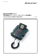
Test Instrument and Adapter 1 2 3 4 5 6 7 2 15 16 17 * * 8 * 14 13 12 11 10 9 * Refer to section 2.1 page 5 regarding usage of the test probes.
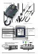
Key Overview of Device Settings and Measuring Functions Test Instrument and Adapter Connections for Current Clamp, Probe and PRO-AB Adapter 1 Control panel with keys and display panel with detent for ideal viewing angle 2 Eyelets for attaching the shoulder strap 3 Rotary selector switch 4 Measuring adapter (2-pole) 5 Plug insert (country specific) 6 Test plug (with retainer ring) 7 Alligator clip (plug-on) 8 Test probes 9 ▼ key ON/START * 10 I key IΔN/compens.
Table of Contents Page Page Scope of delivery ............................................................. 5 10 2 Applications ..................................................................... 5 10.1 10.2 2.1 2.2 Using Cable Sets and Test Probes ...............................................5 Overview of Features Included with PROFITEST MASTER & SECULIFE IP Device Variants ..........6 3 Safety Features and Precautions ..................................... 6 4 Initial Start-Up ............
16.1 16.2 16.3 16.3.1 16.3.2 16.4 16.4.1 Creating Distributor Structures, General ................................... 66 Transferring Distributor Structures ........................................... 66 Creating a Distributor Structure in the Test Instrument ........... 66 Creating Structures (example for electrical circuit) ......................... 67 Searching for Structural Elements ................................................ 68 Saving Data and Generating Reports .................................
Measurement of loop impedance ZL-PE / ZL-N Fuse table for systems without RCDs Without tripping the RCD, fuse table With 15 mA test current 1 without tripping the RCD Earthing resistance RE (mains operation) I-U measuring method (2/3-wire measuring method via measuring adapter: 2-wire/2-wire + probe) Earthing resistance RE (battery operation) 3 or 4-wire measurement via PRO-RE adapter Soil resistivity ρE (battery operation) (4-wire measurement via PRO-RE adapter) Selective earthing resistance RE (mains oper
Any warranty claims will be forfeited when the warranty seal has been damaged or removed. ! When Using a Battery Holder: It is imperative that you pay attention to the correct polarity when inserting the rechargeable batteries. If a battery has been inserted with incorrect polarity, it is not detected by the instrument and may lead to battery leakage. Individual rechargeable batteries may only be charged externally.
4.6 Device Settings SETUP Menu Selection for Operating Parameters 0 1 LED and LCD test menu 2 Rotary switch balancing and battery test menu 0a 3 Brightness/contrast menu Time, language, profiles 0b 4 Software revision level Calibration date 5 Select inspector (change via ETC) Display: date / time Display: automatic shutdown of the tester after 60 s. Display: automatic shutdown of display illumination after 15 s.
Menu Selection for Operating Parameters 0 Display: date / time 1 LED and LCD test menu 2 Rotary switch balancing and battery test menu Display: automatic shutdown of the tester after 60 s. 0a 3 Brightness/contrast menu Time, language, profiles Display: automatic shutdown of display illumination after 15 s.
Significance of Individual Parameters 0a Test Instrument On-Time The period of time after which the test instrument is automatically shut off can be selected here. This selection has a considerable influence on the service life and the charging status of the batteries. 0b On-Time for LCD Illumination The period of time after which LCD illumination is automatically shut off can be selected here. This selection has a considerable influence on the service life and the charging status of the batteries.
3g DB MODE – Presenting the Database in Text Mode or ID Mode ® 3h Switching Bluetooth On/Off (MTECH+/MXTRA/SECULIFE IP only) The DB MODE functions are available as of firmware version 01.05.00 of the test instrument and as of ETC version 01.31.00. Figure 1 Figure 2 Figure 3 Figure 4 Creating Structures in TXT MODE By default, the database in the test instrument is set to text mode, „TXT“ is indicated in the header.
Steps Required for Authentication Make sure that the test instrument is within range of the PC (roughly 5 to 8 meters). Activate Bluetooth® at the test instrument (see figure 1) and at your PC. The function selector switch must be in the SETUP position to this end. Make sure that the test instrument (see figure 3) and your PC are visible for other Bluetooth® devices: In the case of the test instrument, the word “visible” must be displayed underneath the eye symbol.
5 5.1 General Notes Connecting the Instrument For systems with earthing contact sockets, connect the instrument to the mains with the test plug to which the appropriate, country-specific plug insert is attached. Voltage between phase conductor L and the PE protective conductor may not exceed 253 V! Poling at the socket need not be taken into consideration. The instrument detects the positions of phase conductor L and neutral conductor N and automatically reverses polarity if necessary.
5.5 Help Function The following information can be displayed for each switch position and basic function after it has been selected with the rotary selector switch: • Wiring diagram • Measuring range • Nominal range of use and measuring uncertainty • Nominal value ➭ Press the HELP key in order to query online help: ➭ If several pages of help are available for the respective measuring function, the HELP key must be pressed repeatedly. ➭ Press the ESC key in order to exit online help. 5.
5.7 Freely Selectable Parameter Settings or Limit Values In addition to fixed values, other values can be freely selected within predefined limits for certain parameters, if the symbol for the EDIT menu (3) appears at the end of the list of setting values. Freely Selecting a Limit Value or Nominal Voltage 5.
6 Measuring Voltage and Frequency 6.1.2 Voltage between L – PE, N – PE and L – L with 2-Pole Adapter Connection Select Measuring Function U Press the softkey shown at the left in order to switch back and forth between the country-specific plug insert, e.g. SCHUKO, and the 2-pole adapter. The selected connection type is displayed inversely (white on black).
6.2 3-Phase Measurement (line-to-line voltage) and Phase Sequence 7 Testing RCDs The testing of residual current devices (RCDs) includes: • Visual inspection • Testing • Measurement Use the test instrument for testing and measurement. Connection The measuring adapter (2-pole) is required in order to connect the instrument, and can be expanded to a 3-pole measuring adapter with the included measurement cable.
Test Standard The following must be substantiated per DIN VDE 0100 part 600: 2008: – Contact voltage occurring at nominal residual current may not exceed the maximum allowable value for the system. – Tripping of the RCCB must occur within 400 ms (1000 ms for selective RCDs) at nominal residual current. Important Notes • The PROFITEST MASTER allows for simple measurements at all types of RCDs. Select RCD, SRCD, PRCD etc.
1) Measuring Contact Current Without Tripping the RCD 2) Tripping Test after the Measurement of Contact Voltage Measuring Method ➭ Press the IΔN key. The instrument uses a measuring current of only 1/3 nominal residual current for the determination of contact voltage UIΔN which occurs at nominal residual current. This prevents tripping of the RCCB.
7.2 Special Testing for Systems and RCCBs 7.2.1 Testing Systems and RCCBs with Rising Residual Current (AC) for Type AC, A/F, B/B+ and EV/MI RCDs Measuring Method Contact voltage: The instrument generates a continuously rising residual current of (0.3 to 1.3) • IΔN within the system for the testing of RCDs. The instrument stores the contact voltage and tripping current values which were measured at the moment tripping of the RCCB occurred, and displays them.
7.2.3 Testing RCCBS with 5 • IΔN The measurement of time to trip is performed here with 5 times nominal residual current. Note Measurements performed with 5 times nominal fault current are required for testing type S and G RCCBs in the manufacturing process. They are used for personal safety as well. Measurement can be started with the positive half-wave at “0°” or with the negative half-wave at “180°”. Both measurements must nevertheless be performed.
7.3 Tripping Test Testing for Special RCDs 7.3.1 System, Type RCD-S Selective RCCBs Selective RCDs are used in systems which include two series connected RCCBs which are not tripped simultaneously in the event of a fault. These selective RCDs demonstrate delayed response characteristics and are identified with the S symbol. Measuring Method The same measuring method is used as for standard RCCBs (see sections 7.1 on page 18 and 7.2.1 on page 20).
Measuring Method 7.3.3 SRCD, PRCD-S (SCHUKOMAT, SIDOS or comparable) The following can be measured, depending upon the measuring method: • Time to trip tA: tripping test with nominal residual current IΔN (The PRCD-K must be tripped at 50% nominal current.) • Tripping current IΔ: testing with rising residual current IF RCCBs from the SCHUKOMAT SIDOS series, as well as others which are of identical electrical design, must be tested after selecting the corresponding parameter.
7.3.4 Type G or R RCCB In addition to standard RCCBs and selective RCDs, the special characteristics of the type G RCCB can also be tested with the test instrument. The type G RCCB is an Austrian specialty and complies with the ÖVE/ÖNORM E 8601 device standard. Erroneous tripping is minimized thanks to its greater current carrying capacity and shortterm delay.
7.4 Testing Residual Current Circuit Breakers in TN-S Systems Connection 7.5 Testing of RCD Protection in IT Systems with High Cable Capacitance (e.g. in Norway) The desired system type (TN/TT oder IT) can be selected for RCD test type UIΔN (IΔN, ta), and for earthing measurement (RE). A probe is absolutely essential for measurement in IT systems, because contact voltage UIΔN which occurs in these systems cannot otherwise be measured.
8 Testing of Breaking Requirements Overcurrent Protective Devices, Measurement of Loop Impedance and Determination of Short-Circuit Current (functions ZL-PE and IK) Connection: 2-Pole Adapter Testing of overcurrent protective devices includes visual inspection and measurement. Use the PROFITEST MASTER or SECULIFE IP to perform measurements.
8.1.1 Measurement with Positive Half-Waves (only MTECH+/MXTRA/SECULIFE IP) Start Measurement Measurement by means of half-waves plus direct current makes it possible to measure loop impedance in systems which are equipped with RCCBs.
The measured value can only be saved after it has been evaluated. 9 Measuring Line Impedance (ZL-N function) Measuring Method (internal line resistance measurement) Supply impedance ZL-N is measured by means of the same method used for loop impedance ZL-PE (see section 8 on page 26). However, the current loop is completed via neutral conductor N rather than protective conductor PE as is the case with loop impedance measurement. Select Measuring Function ZL-N Connection: Schuko 8.
Start Measurement Polarity selection Semiautomatic measurement See also section 5.8 regarding the AUTO parameter. L-PE relationships are not possible here. The neutral L-N relationship is not offered during automatic sequencing to the right of the auto entry! Settings for Short-circuit current Calculation – Parameter IK IK Limit value: IK < limit value UL ⏐ RL Short-circuit current IK is used to test shutdown by means of an overcurrent protective device.
10 Earthing Resistance Measurement (RE function) Earthing resistance RE is important for automatic shutdown in system segments. It must have a low value in order to assure that high short-circuit current flows and the system is shut down reliably by the RCCB in the event of a fault. Test Setup Earthing resistance (RE) is the sum of the earth electrode’s dissipation resistance and earth conductor resistance.
10.1 Earthing Resistance Measurement – Mains Operated 10.
10.
10.
10.5 Earthing Resistance Measurement, Mains Powered – Measurement of Earth Electrode Voltage (UE function) PRO FITE ST P ter Wa Ri B E1 ipe E2 This measurement is only possible with a probe (see section 10.4). Earth electrode potential UE is the voltage which occurs at the earth electrode between the earth electrode terminal and reference earth if a short-circuit occurs between the phase conductor and the earth electrode.
10.6 Earthing Resistance Measurement, Mains Powered – Selective Earthing Resistance Measurement with Current Clamp Sensor as Accessory As an alternative to the conventional measuring method, measurement can also be performed with a current clamp sensor.
• • In order to prevent electric shock, keep the surface of the METRAFLEX clean and free of contamination. Before use, make sure that the flexible current sensor, the connector cable and the electronics housing are dry. Start Measurement In the event that you have changed the transformation ratio at the test instrument, a pop-up window appears indicating that this new setting also has to be entered to the connected current clamp sensor.
10.7 Earthing Resistance Measurement, Battery Operated – 3-Pole (only MPRO & MXTRA) 3-Wire Method Note The measurement cables must be well insulated in order to prevent shunting. In order to keep the influence of possible coupling to a minimum, the measurement cables should not cross each other or run parallel to each other over any considerable distance.
10.8 Earthing Resistance Measurement, Battery Operated – 4-Pole (only MPRO & MXTRA) 4-Wire Method Note The measurement cables must be well insulated in order to prevent shunting. In order to keep the influence of possible coupling to a minimum, the measurement cables should not cross each other or run parallel to each other over any considerable distance.
➭ Position the probe halfway between the earth electrode and the auxiliary earth electrode and determine earthing resistance. ➭ Reposition the probe 2 to 3 meters closer to the earth electrode, and then 2 to 3 meters closer to the auxiliary earth electrode and measure earthing resistance in each position. If all 3 measurements result in the same measured value, this is the correct earthing resistance. The probe is in the neutral zone.
10.9 Earthing Resistance Measurement, Battery Operated – Selective (4-pole) with Current Clamp Sensor and PRO-RE Measuring Adapter as Accessory (only MPRO & MXTRA) General Set Parameters at Tester PROFITEST MPRO, PROFITEST MXTRA ❑ Measuring range: 200 Ω Note After switching to selective measurement, the AUTO measuring range is activated automatically if a measuring range of greater than 200 Ω had been selected.
10.10 Earthing Resistance Measurement, Battery Powered – Ground Loop Measurement (with current clamp sensor and transformer, plus PRO-RE/2 measuring adapter as accessory) (only MPRO & MXTRA) 2-Clamp Measuring Method Select Measuring Function PROFITEST MPRO, PROFITEST MXTRA RE Select Operating Mode The selected operating mode is displayed inversely: white battery icon against black background.
10.11 Earthing Resistance Measurement, Battery Powered – Measurement of Soil Resistivity ρE (only MPRO & MXTRA) Select Measuring Function RE General H S ES E Select Operating Mode d d d Measurement of Soil Resistivity The determination of soil resistivity is necessary for the planning of earthing systems. Reliable values need to be ascertained which take even the worst possible conditions into account (see “Geologic Evaluation” on page 43).
Geologic Evaluation Calculating Dissipation Resistance Except in extreme cases, the ground is measured down to a depth which is roughly equal to probe distance d. This makes it possible to arrive at conclusions regarding the ground’s stratification by varying probe distance. Layers which are highly conductive (water table), into which earth electrodes should be installed, can thus be discovered within a region which is otherwise poorly conducting.
11 Measuring Insulation Resistance Breakdown current for Ramp Function UINS ! Attention! Limit value: Insulation resistance can only be measured at voltagefree objects. 11.1 General I > ILimit STOP Select Measuring Function RISO RINS Limit values for Breakdown Voltage UINS Connection 2 pole adapter or test plug low limit: upper limit: input range: > 40 V ...
or • As long as you press and hold the ON/START key, test voltage UN is applied and insulation resistance RINS is measured. Do not release the key until the measured value has settled in (settling time may be several seconds in the case of high cable capacitance values). Voltage U, which is measured during testing, corresponds to voltage UINS. After releasing the ON/ START key, measurement is ended and the last measured values for RINS and UINS are displayed.
! Attention! Do not touch the instrument’s terminal contacts during insulation resistance measurements! Test voltage: 50 V / 100 V / 250 V / 325 V / 500 V / 1000 V* If nothing has been connected to the terminal contacts, or if a resistive load component has been connected for measurement, your body would be exposed to a current of approx. 1 mA at a voltage of 1000 V. The noticeable shock may lead to injury (e.g. resulting from a startled reaction etc.).
12 Measuring Low-Value Resistance up to 200 Ohm (protective conductor and equipotential bonding conductor) According to the regulations, the measurement of low-value resistance at protective conductors, earth conductors or bonding conductors must be performed with (automatic) polarity reversal of the test voltage, or with current flow in one (+ pole to PE) and then the other direction (– pole to PE). ! Attention! Low-value resistance must only be measured at voltagefree objects.
12.1 Measurements with Constant Test Current Start Measurement Measuring Low-Value Resistance Measurement cable and 2-pole measuring adapter resistance is compensated for automatically thanks to the four conductor method and thus do not effect measurement results. However, if an extension cable is used its resistance must be measured and deducted from the measurement results.
12.2 Protective Conductor Resistance Measurement with Ramp Curve – Measurements on PRCDs with Current-monitored Protective Conductor Using PROFITEST PRCD Test Adapter as Accessory Application Connection In certain PRCD types, the protective conductor current is monitored. Direct application or disconnection of the test current of 200 mA, which is required for protective conductor resistance measurements, results in tripping of the PRCD and, consequently, a cut-off of the protective conductor connection.
13 Measurement with Accessory Sensors Set Parameters 13.1 Current Measurement with Current Clamp Sensor The transformation ratio parameter must be correspondingly set at the test instrument depending upon the respectively selected measuring range at the current clamp sensor. Bias, leakage and circulating current to 1 A, as well as leakage current to 1000 A can be measured with the help of special current clamp sensors, which are connected to sockets 15 and 16.
14 Special Functions – EXTRA Switch Position Selecting Special Functions The list of special functions is accessed by pressing the uppermost softkey. Select the desired function with the requested icon.
14.1 Voltage Drop Measurement (at ZLN) – ΔU Function Significance and Display of ΔU (per DIN VDE 100, part 600) Voltage drop from the intersection of the distribution network and the consumer system to the point of connection of an electrical power consumer (electrical outlet or device connector terminals) should not exceed 4% of nominal line voltage.
14.2 Measuring the Impedance of Insulating Floors and Walls (standing surface insulation impedance) – ZST Function Start Measurement Measuring Method The instrument measures the impedance between a weighted metal plate and earth. Line voltage available at the measuring site is used as an alternating voltage source. The ZST equivalent circuit is considered a parallel circuit.
14.3 Testing Meter Start-Up with Earthing Contact Plug – kWh Function (not SECULIFE IP) Save Measured Value Energy consumption meters can be tested for correct start-up with this function. Connection L – N Earthing contact plug Special Case Start-up of energy consumption meters which are connected between L and L or L and N can be tested with this function.
14.4 Leakage Current Measurement with PRO-AB Leakage Current Adapter as Accessory – IL Function (PROFITEST MXTRA & SECULIFE IP only) Applications Measuring Sequence Refer to the operating instructions for the PRO-AB leakage current measuring adapter regarding performance of the measurement.
14.5 Testing of Insulation Monitoring Devices – IMD Function (PROFITEST MXTRA & SECULIFE IP only) Set Limit Values for RL-PE as % Applications Insulation monitoring devices (IMDs) or earth fault detection systems (EDSs) are used in IT systems in order to monitor adherence to a minimum insulation resistance value, as specified by DIN VDE 0100-410.
Evaluation Retrieving Saved Measured Values In order to evaluate the measurement, it must be stopped. This applies to manual as well as automatic measurement. Press the “START” or “ESC” key to this end. The stopwatch is stopped and the evaluation window appears. The measured value cannot be saved to memory and included in the test report until it has been evaluated (see also section 16.4). OK NOT OK Press the “NOT OK”, “START” or “ESC” key in order to reject the measurement.
14.6 Residual Voltage Test – Ures Function (PROFITEST MXTRA only) Measuring Sequence – Long-Term Measurement Applications The EN 60204 standard specifies that after switching supply power off, residual voltage must drop to a value of 60 V or less within 5 seconds at all accessible, active components of a machine to which a voltage of greater that 60 V is applied during operation.
14.7 Intelligent Ramp – ta+IΔ Function (PROFITEST MXTRA only) Start Contact Voltage Measurement 14.7.1 Applications The advantage of this measuring function in contrast to individual measurement of IΔN and tA is the simultaneous measurement of breaking time and breaking current by means of a test current which is increased in steps, during which the RCD is tripped only once.
14.8 Testing Residual Current Monitors – RCM Function (PROFITEST MXTRA only) Measure Contact Voltage General Residual current monitors (RCMs) monitor residual current in electrical systems and display it continuously. As is also the case with residual current devices, external switching devices can be controlled in order to shut down supply power in the event that a specified residual current value is exceeded.
14.9 Testing the Operating States of Electric Vehicles at Charging Stations per IEC 61851 (MTECH+ & MXTRA only) A charging station is an equipment designed for the charging of electric vehicles per IEC 61851which essentially consists of a plug connector, a cable protection, a residual current device (RCD), as well as a circuit breaker and a security communication system (PWM).
14.
14.10.
15 Automatic Test Sequences – AUTO Function If the same order of tests with subsequent report generation is to be performed repeatedly, as is, for example, specified by certain standards, we recommend using test sequences. With the help of test sequences it is possible to compile automatic test procedures on the basis of the manual individual measurements. A test sequence consists of up to 200 individual test steps which have to be processed one after the other.
Please note that the test sequences loaded to the test instrument are deleted by the following operations in the test instrument: • • • • • • • Selecting and Starting a Test Sequence at the Test Instrument Figure 15.
16 Database 16.1 Creating Distributor Structures, General A complete distributor structure with data for electrical circuits and RCDs can be created in the PROFITEST MASTER test instrument. This structure makes it possible to assign measurements to the electrical circuits of various distributors, buildings and customers. There are two possible procedures: • On location or at the construction site: Create the distributor structure in the test instrument.
Icon Meaning Show measurement data, if a measurement has been performed for this structural element. Edit the selected structural element. Memory menu, page 3 of 3 Search for ID number. > Enter complete ID number. Search for text. > Enter full text (complete word). Search for ID number or text. Distributor Structure Symbology / Tree Structure A check mark to the right of a structural element means that all measurements within the respective hierarchy have been passed.
Select a new object from a list. 16.3.2 Searching for Structural Elements Scroll up Scroll up Scroll down Scroll down Acknowledge selection Acknowledge selection / change level Display object or ID number Menu selection → page 3/3 Select the desired object from the list with the ↑↓ keys and acknowledge with the ↵ key. Depending upon the profile selected in the test instrument’s SETUP menu (see section 4.6), the number of object types may be limited, and the hierarchy may be laid out differently.
Note Search for ID number Search for text Search for ID number or text End search If no further matches are found, the message shown above is displayed. 16.4 Saving Data and Generating Reports Preparing and Executing a Measurement Measurements can be performed and stored to memory for each structural element. Proceed as follows, adhering to the prescribed sequence: ➭ Select the desired measurement with the rotary knob. ➭ Start the measurement by pressing the ON/START or IΔN key.
Data Evaluation and Report Generation with ETC Software All data, including the distributor structure, can be transferred to the PC and evaluated with the help of ETC software. Additional information can be entered here subsequently for the individual measurements. After pressing the appropriate key, a report including all measurements within a given distributor structure is generated, or the data are exported to an Excel spreadsheet. Note The database is exited when the rotary selector switch is turned.
17 Operating and Display Elements Test Instrument and Adapter (1) Control Panel – Display Panel The following are displayed at the LCD: • One or two measurement values as three place numeric display with unit of measure and abbreviated measured quantity • Nominal values for voltage and frequency • Circuit diagrams • On-line help • Messages and instructions The display and control panel can be swiveled forward or backward with the detented swivel hinge.
The instrument determines whether or not the probe has been properly set and displays results at the display panel. (18) USB Port The USB port allows for the exchange of data between the test instrument and a PC. (19) RS 232 Port This connection allows for data entry by means of a barcode scanner or an RFID reader. (20) Charging Socket This socket may only be used to connect the Z502R charger for recharging batteries in the instrument.
18 LED Indications, Mains Connections and Potential Differences Status Test plug Meas. Position of the Adapter Function Switch Function / Meaning LED Indications NETZ/ MAINS Lights up green NETZ/ MAINS Blinks green X NETZ/ MAINS Lights up orange X NETZ/ MAINS Blinks red X X X NETZ/ MAINS NETZ/ MAINS Lights up red X Blinks Yellow X UL/RL Lights up red FI/RCD Lights up red X X IΔN / IF ZL-N / ZL-PE / RE ΔU, ZST, kWh, IMD, int.
Status Test Meas.
Status Test plug Meas. Position of the Adapter Function Switch Function / Meaning Battery Test is displayed All Rechargeable batteries must be recharged, or replaced towards the end of their service life (U < 8 V).
Status Test plug Meas. Position of the Adapter Function Switch All X Excessive temperature inside the test instrument Remedy: wait for test instrument to cool down Interference voltage Remedy: device under test must be disconnected from all sources of voltage Interference voltage > 20 V at the probes: H to E or S to E no measurement possible X RINS / RLO PRO-RE RE (bat) PRO-RE RE (bat) Probe ES not connected or connected wrong.
Status Test plug Meas. Position of the Adapter Function Switch X X X X RE IΔN / IF X IΔN / IF ZL-N / ZL-PE / RE IΔN / IF RE IΔN / IF Function / Meaning The polarity of the 2-pole adapter must be reversed. N and PE are swapped. 1) Mains connection error Remedy: Inspect mains connection.
Status Test Meas.
Status Test plug Meas. Position of the Adapter Function Switch RE 15 mA only possible in the 1 kΩ and 100 Ω range! RE 15 mA only as loop measurement with or without probe EXTRA → RCM IΔN / IF With RCM: TYPE AC, F , B, B+ and EV/MI not possible No measurement with half-wave or DC in the IT network All The parameters you have selected do not make sense in combination with previously configured parameters. The selected parameter settings will not be saved. Remedy: Enter other parameter settings.
Status Test Meas. Position of the plug Adapter Function Switch Messages — LCD Pictographs — Test sequences Function / Meaning AUTO The test sequence includes a measurement which cannot be processed by the connected test instrument. The respective test step must be skipped. Example: The test sequence includes a RCM measurement which has been transferred to PROFITEST MTECH. AUTO The test sequence has been successfully completed. AUTO There are no test sequences available.
Status Test Meas. Position of the plug Adapter Function Switch Database and Entry Operations — LCD Pictographs IΔN / IF ZL-N / ZL-PE EXTRA → tA+IΔ EXTRA → RCM Function / Meaning Saving a measured value with differing electrical circuit parameter The electrical circuit parameter you have set at the test instrument does not correspond to the parameter saved in the structure under object data.
19 Characteristic Values Characteristic Values MBASE+ & MTECH+ Function Measured Quantity Resolution 0.1 V 1V 0.1 Hz 1 Hz 0.1 V 1V 0.1 V 1V 0.1 V 1V 5 MΩ UL-N 0 ... 99.9 V 100 ... 600 V 15.0 ... 99.9 Hz 100 ... 999 Hz 0 ... 99.9 V 100 ... 600 V 0 ... 99.9 V 100 ... 600 V 0 ... 99.9 V 100 ... 600 V UIΔN 0 ... 70.0 V 0.1 V 0.
Connections Function Measured Quantity RINS. RE INS RINS U RLO RLO Display Range 1 ... 999 kΩ 1.00 ... 9.99 MΩ 10.0 ... 49.9 MΩ 1 ... 999 kΩ 1.00 ... 9.99 MΩ 10.0 ... 99.9 MΩ 1 ... 999 kΩ 1.00 ... 9.99 MΩ 10.0 ... 99.9 MΩ 100 ... 200 MΩ 1 ... 999 kΩ 1.00 ... 9.99 MΩ 10.0 ... 99.9 MΩ 100 ... 500 MΩ 10 ... 999 V– 1.00 ... 1.19 kV 0.01 Ω ... 9.99 Ω 10.0 Ω ... 99.9 Ω Resolution Test Current 1 kΩ 10 kΩ 100 kΩ 1 kΩ 10 kΩ 100 kΩ 1 kΩ IK = 1.
Characteristic Values MPRO, MXTRA & SECULIFE IP Function Display Range Input ResoImpedance / lution Test Current 0.1 V 1V 0.1 Hz 1 Hz 0.1 V 1V 0.1 V 1V 0.1 V 1V 5 MΩ UL-N 0 ... 99.9 V 100 ... 600 V 15.0 ... 99.9 Hz 100 ... 999 Hz 0 ... 99.9 V 100 ... 600 V 0 ... 99.9 V 100 ... 600 V 0 ... 99.9 V 100 ... 600 V UIΔN 0 ... 70.0 V 0.1 V 0.3 · IΔN Measured Quantity UL-PE UN-PE f U U3~ UProbe Connections Measuring Range 0.3 ... 600 V 1 DC 15.4 ... 420 Hz 0.3 ... 600 V 1.0 ... 600 V 1.0 ...
Connections Function RINS Measured Quantity RINS, RE ISO U RLO RLO Display Range 1 ... 999 kΩ 1.00 ... 9.99 MΩ 10.0 ... 49.9 MΩ 1 ... 999 kΩ 1.00 ... 9.99 MΩ 10.0 ... 99.9 MΩ 1 ... 999 kΩ 1.00 ... 9.99 MΩ 10.0 ... 99.9 MΩ 100 ... 200 MΩ 1 ... 999 kΩ 1.00 ... 9.99 MΩ 10.0 ... 99.9 MΩ 100 ... 500 MΩ 10 ... 999 V– 1.00 ... 1.19 kV 0.01 Ω ... 9.99 Ω 10.0 Ω ... 199.
Characteristic Values PROFITEST MASTER & SECULIFE IP Reference Conditions 230 V ± 0.1% 50 Hz ± 0.1% 45 Hz … 65 Hz Sine (deviation between effective and rectified value ≤ 0.1%) cos ϕ = 1 ≤ 10 Ω 12 V ± 0.5 V + 23 °C ± 2 K 40% … 60% For testing potential difference to ground potential Purely ohmic Line voltage Line frequency Meas. quantity frequency Measured qty.
20 20.1 Maintenance 20.3 Firmware Revision and Calibration Information If a fuse has blown due to overload, a corresponding message error appears at the display panel. The instrument’s voltage measuring ranges are nevertheless still functional. See section 4.6. 20.2 Rechargeable Battery Operation, and Charging Check to make sure that no leakage has occurred at the rechargeable batteries at short, regular intervals, or after the instrument has been in storage for a lengthy period of time.
21 Appendix 21.1 Tables for the determination of maximum or minimum display values under consideration of maximum measuring uncertainty: Table 1 Table 3 ZL-PE. (full wave) / ZL-N (Ω) Limit Max. DisValue play Value 0.10 0.07 0.15 0.11 0.20 0.16 0.25 0.20 0.30 0.25 0.35 0.30 0.40 0.34 0.45 0.39 0.50 0.43 0.60 0.51 0.70 0.60 0.80 0.70 0.90 0.79 1.00 0.88 1.50 1.40 2.00 1.87 2.50 2.35 3.00 2.82 3.50 3.30 4.00 3.78 4.50 4.25 5.00 4.73 6.00 5.68 7.00 6.63 8.00 7.59 9.00 8.54 9.99 9.48 ZL-PE.
Table 5 ZST kΩ Limit Value Min.
21.2 At which values should/must an RCD actually be tripped? Requirements for Residual Current Devices (RCDs) Set residual current type or waveform at the test instrument: General Requirements • Tripping must occur no later than upon occurrence of rated residual current (nominal differential current IΔN). and • Maximum time to trip may not be exceeded.
Tests for electrical systems include “visual inspection”, “testing” and “measurement”, and thus may only be conducted by experts with appropriate work experience. In the final analysis, the values from VDE 0664 are technically binding. Function Test The machine is operated with nominal voltage and tested for correct functioning, in particular with regard to safety functions. Special Tests 21.
21.4 Periodic Testing per DGUV provision 3 (previously BGV A3) – Limit Values for Electrical Systems and Operating Equipment Limit Values per DIN VDE 0701-0702 Maximum Allowable Limit Values for Protective Conductor Resistance for Connector Cables with Lengths of up to 5 m Test Standard Test Current Open-Circuit Voltage RSL Housing – Mains Plug 0.3 Ω 1 VDE 0701-0702:2008 1 2 > 200 mA 4 V < UL < 24 V + 0.1 Ω 2 for each additional 7.
21.
21.6 Keyword Index A Abbreviations ..........................................................................93 Adjusting Brightness and Contrast ..........................................10 B Batteries Charge Level .....................................................................3 Installation ..........................................................................7 Battery Test ...................................................................................7 Bibliography ......................
21.7 Bibliography 21.7.1 Internet Addresses for Additional Information Statutory Source Documents Internet Address German occupational safety legislation (BetrSichV) Regulations issued by the accident insurance carriers Title Information Rule / Regulation Publisher Issue / Order No.
22 Repair and Replacement Parts Service Calibration Center* and Rental Instrument Service If required please contact: GMC-I Service GmbH Service-Center Thomas-Mann-Strasse 16-20 90471 Nürnberg, Germany Phone: +49 911 817718-0 Fax: +49 911 817718-253 E-mail service@gossenmetrawatt.com www.gmci-service.com This address is only valid in Germany. Please contact our representatives or subsidiaries for service in other countries.