
User manual


GMC-I Messtechnik GmbH 5
16.1 Creating Distributor Structures, General ................................... 66
16.2 Transferring Distributor Structures ........................................... 66
16.3 Creating a Distributor Structure in the Test Instrument ........... 66
16.3.1 Creating Structures (example for electrical circuit) ......................... 67
16.3.2 Searching for Structural Elements ................................................ 68
16.4 Saving Data and Generating Reports ........................................ 69
16.4.1 Use of Barcode Scanners and RFID Readers ................................. 70
17 Operating and Display Elements ....................................71
18 LED Indications, Mains Connections and Potential Differen-
ces ..................................................................................73
19 Characteristic Values ......................................................82
20 Maintenance ...................................................................87
20.1 Firmware Revision and Calibration Information ....................... 87
20.2 Rechargeable Battery Operation, and Charging ....................... 87
20.2.1 Charging Procedure with Charger for Z502R ................................. 87
20.3 Fuses ........................................................................................ 87
20.4 Housing ..................................................................................... 87
21 Appendix .........................................................................88
21.1
Tables for the determination of maximum or minimum display values un-
der consideration of maximum measuring uncertainty: .......................88
21.2 At which values should/must an RCD actually be tripped?
Requirements for Residual Current Devices (RCDs) ................. 90
21.3 Testing Electrical Machines per DIN EN 60204 –
Applications, Limit Values ......................................................... 91
21.4 Periodic Testing per DGUV provision 3 (previously BGV A3) – Limit
Values for Electrical Systems and Operating Equipment .......... 92
21.5 List of Abbreviations and their Meanings ................................. 93
21.6 Keyword Index .......................................................................... 94
21.7 Bibliography .............................................................................. 95
21.7.1 Internet Addresses for Additional Information ............................... 95
22 Repair and Replacement Parts Service
Calibration Center and Rental Instrument Service .........96
23 Recalibration ..................................................................96
24 Product Support .............................................................96
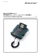
1 Scope of delivery
1Test instrument
1 Earthing contact plug insert (country-specific)
1 2-pole measuring adapter and 1 cable for expansion into a
3-pole adapter (PRO-A3-II)
2 Alligator clips
1 Shoulder strap
1 Compact Master Battery Pack (Z502H)
1 Charger Z502R
1 DAkkS calibration certificate
1USB cable
1 Condensed operating instructions
1 Supplement Safety Information
– Detailed operating instructions for download from our website
at www.gossenmetrawatt.com
2 Applications
This instrument fulfills the requirements of the applicable EU
guidelines and national regulations. We confirm this with the CE
marking. The relevant declaration of conformity can be obtained
from GMC-I Messtechnik GmbH.
The PROFITEST MASTER and SECULIFE IP measuring and test instru-
ments allow for quick and efficient testing of protective measures
in accordance with DIN VDE 0100, part 600:2008
(Erection of low-
voltage installations; tests – initial tests), as well as
ÖVE-EN 1
(Austria), NIV/NIN SEV 1000 (Switzerland) and other country-spe-
cific regulations.
The test instrument is equipped with a microprocessor and com-
plies with IEC 61557/DIN EN 61557/VDE 0413 regulations:
Part 1: General requirements
Part 2: Insulation resistance
Part 3: Loop resistance
Part 4:
Resistance of earth connection and equipotential bonding
Part 5: Earth resistance
Part 6: Effectiveness of residual current devices (RCD) in TT, TN
and IT systems
Part 7: Phase sequence
Part 10:Electrical safety in low-voltage systems up to 1000 V AC
and 1500 V DC – Equipment for testing, measuring or
monitoring of protective measures
Part 11:Effectiveness of type A and type B residual current moni-
tors (RCMs) in TT, TN and IT systems
The test instrument is especially well suited for:
•System setup
• Initial start-up
• Periodic testing
• Troubleshooting in electrical systems
All of the values required for approval reports (e.g. for ZVEH) can
be measured with this instrument.
All acquired data can be archived, in addition to the measurement
and test reports which can be printed out at a PC. This is of spe-
cial significance where product liability is concerned.
The applications range of the test instruments covers all alternat-
ing and three-phase current systems with nominal voltages of
230 V / 400 V (300 V / 500 V) and nominal frequencies of 16
2
/
3
/
50 / 60 / 200 / 400 Hz.
The following can be measured and tested with the instruments:
• Voltage / frequency / phase sequence
• Loop impedance / line impedance
• Residual current devices (RCDs)
• Insulation monitoring devices (IMDs) (only
MXTRA
&
SECULIFE IP
)
• Residual current monitoring devices (RCMs) (only MXTRA)
• Earthing resistance / earth electrode potential
• Standing surface insulation resistance / insulation resistance
• Earth leakage resistance
• Low-value resistance (potential equalization)
• Leakage currents with current transformer clamp
• Residual voltage (only MXTRA)
• Voltage drop
• Leakage current with leakage current adapter
• Meter start-up (not
SECULIFE IP
)
• Cable length
Refer to section 21.3 regarding testing of electrical machines in
accordance with DIN EN 60204.
Refer to section 21.4 regarding periodic testing in accordance
with DGUV provision 3 (previously BGV A3).
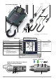
2.1 Using Cable Sets and Test Probes
• 2 or 3-pole measuring adapter included
• 2-pole measuring adapter with 10 m cable as optional acces-
sory: PRO-RLO II (Z501P)
• KS24 cable set as optional accessory (GTZ3201000R0001)
Measurements per DIN EN 61010-031 may only be performed in
environments in accordance with measuring categories III and IV
with the safety cap attached to the test probe at the end of the
measurement cable.
In order to establish contact inside 4 mm jacks, the safety caps
have to be removed by prying open the snap fastener with a
pointed object (e.g. the other test probe).