
User manual


GMC-I Messtechnik GmbH 83
1
U > 253 V, with 2 or 3-pole adapter only
2
1
·
/ 2
·
IN > 300 mA and 5
·
IN > 500 mA and If > 300 mA only up to U
N
≤ 230 V !
IN 5
·
300 mA only with U
N
= 230 V
3
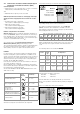
The transformation ratio selected at the clamp (1 ... 1000 mV/A) must be set in the
“Type” menu with the rotary switch in the “SENSOR” position.
4
at R
Eselektiv
/R
Egesamt
< 100
5
the indicated measuring and intrinsic uncertainties already include the uncertainties
of the respective current clamp.
6
Measuring range of the signal input at the test instrument U
E
: 0 ... 1.0 V
eff
(0 ... 1.4
Vpeak) AC/DC
7
Input impedance of signal input at the test instrument: 800 kΩ
8
for f
N
< 45 Hz => U
N
< 253 V
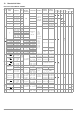
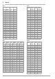
Key: D = digits, rdg. = measured value (reading)
Func-
tion
Measured
Quantity
Display Range
Reso-
lution
Test Current Measuring Range Nominal Values
Measuring
Uncertainty
Intrinsic
Uncertainty
Connections
Plug
Insert
1
2-Pole
Adapter
3-Pole
Adapter
Clamps
WZ12C Z3512A
MFLEX
P300
CP1100
R
INS
R
INS
. R
E INS
1 ... 999 kΩ
1.00 ... 9.99 MΩ
10.0 ... 49.9 MΩ
1 kΩ
10 kΩ
100 kΩ
I
K
= 1.5 mA 50 kΩ ... 500 MΩ
U
N
= 50 V
I
N
= 1 mA
kΩ range
±(5% rdg.+10d)
MΩ range
±(5% rdg.+1d)
kΩ range
±(3% rdg.+10d)
MΩ range
±(3% rdg.+1d)
●●
1 ... 999 kΩ
1.00 ... 9.99 MΩ
10.0 ... 99.9 MΩ
1 kΩ
10 kΩ
100 kΩ
U
N
= 100 V
I
N
= 1 mA
1 ... 999 kΩ
1.00 ... 9.99 MΩ
10.0 ... 99.9 MΩ
100 ... 200 MΩ
1 kΩ
10 kΩ
100 kΩ
1 MΩ
U
N
= 250 V
I
N
= 1 mA
1 ... 999 kΩ
1.00 ... 9.99 MΩ
10.0 ... 99.9 MΩ
100 ... 500 MΩ
1 kΩ
10 kΩ
100 kΩ
1 MΩ
U
N
= 500 V/
1000 V
I
N
= 1 mA
U
10 ... 999 V–
1.00 ... 1.19 kV
1 V
10 V
10 ... 1.19 kV ±(3% rdg.+1d)
±
(1.5% rdg.+1d)
R
LO
R
LO
0.01 Ω ... 9.99 Ω
10.0 Ω ... 99.9 Ω
10 mΩ
100 mΩ
I
m
≥ 200 mA
I
m
< 200 mA
0.1 Ω ... 5.99 Ω
6.0 Ω ... 100 Ω
U
0
= 4.5 V ±(4% rdg.+2d) ±(2% rdg.+2d)
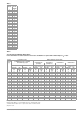
●
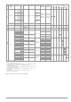
Transforma-
tion
ratio
3
55
SEN-
SOR
6
7
I
L/Amp
0.0 ... 99.9 mA 0.1 mA
1 V/A 5 ... 15 A
f
N
= 50/60 Hz
±(13% rdg.+5d) ±(5% rdg.+4d)
I 15A
100 ... 999 mA 1 mA
±(13% rdg.+1d) ±(5% rdg.+1d)1.00 ... 9.99 A 0.01 A
10.0 ... 15.0 A 0.1 A
1.00 ... 9.99 A 0.01 A
1 mV/A 5 ... 150 A
±(11% rdg.+4d) ±(4% rdg.+3d)
II 150A
10.0 ... 99.9 A 0.1 A
±(11% rdg.+1d) ±(4% rdg.+1d)
100 ... 150 A 1 A
0.0 ... 99.9 mA 0.1 mA
1 V/A 5 ... 1000 mA
f
N
=
16.7/50/60/
200/400 Hz
±(7% rdg.+2 d) ±(5% rdg.+2 d)
1 A
100 ... 999 mA 1 mA ±(7% rdg.+1 d) ±(5% rdg.+1 d)
0.00 ... 9.99 A 0.01 A 100 mV/A 0.05 ... 10 A ±(3.4% rdg.+2 d) ±(3% rdg.+2 d)
10 A
0.00 ... 9.99 A 0.01 A
10 mV/A 0.5 ... 100 A
±(3.1% rdg.+2 d) ±(3% rdg.+2 d)
100 A
10.0 ... 99.9 A 0.1 A ±(3.1% rdg.+1 d) ±(3% rdg.+1 d)
0.00 ... 9.99 A 0.01 A
1 mV/A 5 ... 1000 A
±(3.1% rdg.+1 d) ±(3% rdg.+1 d)
1000A
10.0 ... 99.9 A 0.1 A ±(3.1% rdg.+2 d) ±(3% rdg.+2 d)
100 ... 999 A 1 A ±(3.1% rdg.+1 d) ±(3% rdg.+1 d)
0.0 ... 99.9 mA 0.1 mA
1 V/A 30 ... 1000 mA
f
N
= 50/60 Hz
±(27% rdg.+100 d) ±(3% rdg.+100 d)
0.03
100 ... 999 mA 1 mA
±(27% rdg.+11 d)
±(3% rdg.+11 d)
3
0.00 ... 9.99 A
0.01 A
100 mV/A 0.3 ... 10 A
±(27% rdg.+12 d)
±(3% rdg.+12 d)
0.3
0.01 A
±(27% rdg.+11 d)
±(3% rdg.+11 d)
30
0.00 ... 9.99 A 0.01 A
10 mV/A 3 ... 100 A
±(27% rdg.+100 d) ±(3% rdg.+100 d)
3
10.0 ... 99.9 A 0.1 A
±(27% rdg.+11 d)
±(3% rdg.+11 d)
300
0.00 ... 9.99 A 0.01 A
10 mV/A 0.5 ... 100 A
f
N
=
DC/16.7/50/60/
200 Hz
±
(5% rdg.+12 d)
±
(3% rdg.+12 d)
100A
~
10.0 ... 99.9 A 0.1 A ±(5% rdg.+2 d)
±(3% rdg.+2 d)
0.00 ... 9.99 A 0.01 A
1 mV/A 5 ... 1000 A
±
(5% rdg.+50 d) ±(3% rdg.+50 d)
1000A
~
10.0 ... 99.9 A 0.1 A ±(5% rdg.+7 d)
±(3% rdg.+7 d)
100 ... 999 A 1 A ±(5% rdg.+2 d)
±(3% rdg.+2 d)