Operating Instructions PROFITEST INTRO 3-349-840-03 5/1.
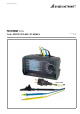
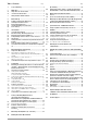
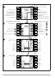
LCD Panel Rotary Selector Switch Guide for Carrying Strap Guide for Carrying Strap Setup Menu Control Panel • • • • Softkeys Parameter selection Limit value specification Entry functions Memory functions MAINS/NETZ LED → see below Limit LED → see below Fixed Function Keys ESC: Return from submenu / Activate instrument from standby state MEM: Key for memory functions HELP: Access context sensitive help START:Switch on / start measurement I∆N: Triggering key / compensation (offset) LED Indications (
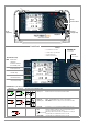
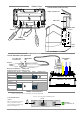
Batteries, Fuses Inserting the Battery Holder (side view) Battery Compartment Lid a Battery Holder b Battery Holder Contacts Battery Compartment Fuses Battery Compartment Lid Contact Spring user interface Measuring Connections Test Probe with Remote Control, Option Z550A Measurement Key Z550A Option Key for Measuring Point Illumination Test probe Measuring Point Illumination Optional Z503K Z503L Safety Collar Assignment of Keys to Device or Remote Control Measuring Function At Device Via Rem
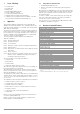
Key Overview of Device Settings and Measuring Functions Connection test → section 16 Display Panel Battery display Measuring function Measurement in PE progress / stopped Memory occupancy RUN READY Parameter Switch PictoSetting graph description as of SETUP Device settings Measuring Functions Brightness, contrast, time/date Language (D, GB, P), profiles (ETC, PS3, PC.
Table of Contents 1 Page Page Scope of Delivery .............................................................. 6 (RE function) ...................................................................29 10.1 Earth Resistance, Mains Operation – 2-Pole Measurement with KSPROFITEST INTRO or Country-Specific Measuring Adapter (Schuko) ..30 2 Application ........................................................................ 6 2.1 2.2 Using Cable Sets and Test Probes .........................................
1 1 1 1 1 1 1 1 1 2 Scope of Delivery Test instrument Shoulder strap Battery pack KS-PROFiTEST INTRO (Z503L) Factory calibration certificate Condensed operating instructions Supplementary sheet with safety information Comprehensive operating instructions available on the Internet for download at www.gossenmetrawatt.com Application This instrument fulfills the requirements of the applicable EU guidelines and national regulations. We confirm this with the CE mark.
3 Safety Features and Precautions The electronic measuring and test instrument is manufactured and tested in accordance with safety regulations IEC 61010-1/ EN 61010-1/VDE 0411-1. Safety of the operator, as well as that of the instrument, is only assured when it’s used for its intended purpose. Read the operating instructions thoroughly and carefully before using your instrument. Follow all instructions contained therein.
4 Initial Start-Up 4.1 ! Installing or Replacing the Battery Pack Attention! Before opening the battery compartment, disconnect the instrument from the measuring circuit (mains) at all poles! Note See also section 18.2 on page 52 regarding the charging procedure for the Compact Master Battery Pack (Z502H) and concerning the Z502R charger. If at all possible, use the Compact Master Battery Pack (Z502H) with sealed cells which is available as an accessory.
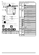
4.5 Device Settings SETUP Menu Selection for Operating Parameters 0 Display: date / time LED, LCD and acoustic signal test menu 2 Battery test Display: automatic shutdown of the tester after 120 s. 0a 3 OFFSET, brightness/contrast menu Time, language, profiles Display: automatic shutdown of display illumination after 20 s.
Menu Selection for Operating Parameters 0 Display: date / time 1 LED and LCD test menu 2 Menu Battery test Display: automatic shutdown of the tester after 60 s. 0a 3 Brightness/contrast menu Time, language, profiles Display: automatic shutdown of display illumination after 15 s.
Significance of Individual Parameters 0a Test Instrument On-Time The period of time after which the test instrument is automatically shut off can be selected here. This selection has a considerable influence on the service life and the charging status of the batteries. 0b LCD Illumination On-Time The period of time after which LCD illumination is automatically shut off can be selected here. This selection has a considerable influence on the service life and the charging status of the batteries.
If no texts or ID numbers have been entered to the test instrument when creating structures, ETC generates the missing entries automatically. These can then be edited in ETC and transferred back to the test instrument if required. 3h OFFSET RL-PE / RN-PE / RL-N For the measurement of ZL-PE, ZL-N, RE and ∆U(ZLN), ohmic offset values RL-PE, RN-PE and RL-N can be ascertained here, which then appear in the footers of the corresponding measuring menu pages and are subtracted from the measured values.
Measurement of Touch Voltage via Finger Contact 5.3 When a measurement is started and if you touch the ON/START key with your finger, the test instrument detects whether or not dangerous touch voltage Ub is present at the PE terminal relative to ground.
5.5 Help Function The following information can be displayed for each switch position and basic function after it has been selected with the rotary selector switch: • Wiring diagram • Measuring range • Nominal range of use and measuring uncertainty • Nominal value ➭ Press the HELP key in order to query online help. ➭ If several pages of help are available for the respective measuring function, the HELP key must be pressed repeatedly. ➭ Press the ESC key in order to exit online help. 5.
5.7 Freely Selectable Parameter Settings or Limit Values In addition to fixed values, other values can be freely selected within predefined limits for certain parameters, if the symbol for the EDIT menu (3) appears at the end of the list of setting values. Freely Selecting a Limit Value or Nominal Voltage Select editable value. Select editable value. 3 4 5.
6 Measuring Voltage and Frequency 6.1.2 Voltage Between L – PE, N – PE and L – L with 2-Pole Connection Select the Measuring Function Press the softkey shown at the left in order to switch back and forth between the country-specific measuring adapter, e.g. PRO-Schuko measuring adapter (Z503K), and 2-pole measurement with the KSPROFITEST INTRO (Z503L). The selected connection type is displayed inversely (white on black).
6.2 3-Phase Measurement (line-to-line voltage) and Phase Sequence 7 Testing RCDs Testing of residual current devices (RCDs) includes: • Visual inspection • Testing • Measurement Use the test instrument for testing and measurement. Connection The included measurement cables (Z503L) are required in order to connect the instrument.
Test Standard 7.1 The following must be substantiated per DIN VDE 0100-600:2008: – Touch voltage occurring at nominal residual current may not exceed the maximum allowable value for the system. – Tripping of the RCCB must occur within 400 ms (1000 ms for selective RCDs) at nominal residual current.
1) Measuring Touch Current Without Tripping the RCD 2) Tripping Test after the Measurement of Touch Voltage Measuring Method ➭ Press the I∆N key The instrument uses a measuring current of only ⅓ nominal residual current for the determination of touch voltage UI∆N which occurs at nominal residual current. This prevents tripping of the RCCB. This measuring method is especially advantageous, because touch voltage can be measured quickly and easily at any electrical outlet without tripping the RCCB.
7.2 Special Tests for Systems and RCDs 7.2.1 Testing Systems and RCCBs with Rising Residual Current (AC) for Type AC, A/F, B/B+ and EV, MI RCDs Touch voltage: Measuring Method The instrument generates a continuously rising residual current of (0.3 ... 1.3) • I∆N within the system for the testing of RCDs. The instrument stores the touch voltage and tripping current values which were measured at the moment tripping of the RCCB occurred, and displays them.
Testing RCCBS with 5 • I∆N 7.2.3 Measurement of time to trip is performed here with 5 times nominal residual current. Note Measurements performed with 5 times nominal fault current are required for testing type S and G RCCBs in the manufacturing process. They are used for personal safety as well. 7.2.4 Testing of RCCBs Pulsating DC Residual Current In this case, RCCBs can be tested with either positive or negative half-waves. The standard calls for tripping at 1.4 times nominal current.
7.3 Testing of Special RCDs 7.3.1 Systems with Type RCD-S Selective RCCBs Selective RCCBs are used in systems which include two series connected RCCBs that are not tripped simultaneously in the event of a fault. These selective RCCBs demonstrate delayed response characteristics and are identified with the S symbol. Measuring Method The same measuring method is used as for standard RCCBs (see sections 7.1 on page 18 and 7.2.1 on page 20).
Measuring Method 7.3.3 The following can be measured, depending upon the measuring method: • Time to trip tA: tripping test with nominal residual current I∆N (the PRCD-K must be tripped at 50% nominal current). • Tripping current I∆ for testing with rising residual current IF RCCBs from the SCHUKOMAT SIDOS series, as well as others which are of identical electrical design, must be tested after selecting the corresponding parameter. Monitoring of the PE conductor is performed for RCDs of this type.
7.3.4 Type G or R RCCB Set the Parameter – 5 Times Nominal Current In addition to standard RCCBs and selective RCDs, the special characteristics of the type G RCCB can also be tested with the test instrument. The type G RCCB is an Austrian specialty and complies with the ÖVE/ÖNORM E 8601 device standard. Erroneous tripping is minimized thanks to its greater current carrying capacity and shortterm delay.
8 Testing of Breaking Requirements for Overcurrent Protective Devices, Measurement of Loop Impedance and Determination of Short-Circuit Current (functions ZL-PE and IK) Select the Measuring Function ZL-PE Testing of overcurrent protective devices includes visual inspection and measurement. Use the PROFITEST INTRO to perform measurements.
8.1 Measurements with Suppression of RCD Tripping 8.1.1 Measurement with Positive Half-Waves Measurement by means of half-waves plus direct current makes it possible to measure loop impedance in systems which are equipped with RCCBs.
Special Case: Suppressing Display of the Limit Value The limit value cannot be ascertained. The inspector is prompted to evaluate the measured values himself, and to acknowledge or reject them with the help of the softkeys. Measurement passed: ✔ key Measurement failed: X key The measured value can only be saved after it has been evaluated.
Measurement Cable Compensation The resistance of the respectively connected measurement cable or the country-specific measuring adapter must be compensated for each line impedance measurement, i.e. it must be subtracted from the measurement results as an offset. Proceed as described in section 4.5 under „OFFSET RL-PE / RN-PE / RL-N“ on page 12 to this end in order to ascertain offset values RLPE-OFFSET and RNPE-OFFSET Polarity selection Start Measurement Semiautomatic measurement See also section 5.
10 Earthing Resistance Measurement (RE function) Earthing resistance RE is important for automatic shutdown in system segments. It must have a low value in order to assure that high short-circuit current flows and the system is shut down reliably by the RCCB in the event of a fault. Test Setup Earthing resistance (RE) is the sum of the earth electrode’s dissipation resistance and earth conductor resistance.
10.
Measurement Cable Compensation The resistance of the respectively connected measurement cable or the country-specific measuring adapter must be compensated for each earth resistance measurement, i.e. it must be subtracted from the measurement results as an offset. Proceed as described in section 4.5 under „OFFSET RL-PE / RN-PE / RL-N“ on page 12 to this end in order to ascertain offset values RLPE-OFFSET and RNPE-OFFSET.
11 ! Measurement of Insulation Resistance Polarity Selection 2-pole measurement (selection relevant for report generating only), measurements between: Lx-PE / N-PE / L+N-PE / Lx-N / Lx-Ly / AUTO* where x, y = 1, 2, 3 Attention! Insulation resistance can only be measured at voltagefree objects. * AUTO parameter (see section 5.8) 11.
The constant test voltage function offers two options: • After briefly pressing the ON/START key, specified test voltage UN is read out and insulation resistance RINS is measured. As soon as the measured value is stable (settling time may be several seconds in the case of high cable capacitance values), measurement is ended and the last measured values for RINS and UINS are displayed. U is the voltage which is measured at the test probes during and after testing.
Special Condition for Insulation Resistance Measurement ! Set Parameters Attention! Test voltage: 50 V / 100 V / 250 V / 325 V / 500 V / 1000 V* Insulation resistance can only be measured at voltagefree objects. If measured insulation resistance is less than the selected limit value, the LIMIT LED lights up. If an interference voltage of ≥ 25 V is present within the system, insulation resistance is not measured. The MAINS/NETZ LED lights up and the “interference voltage” pop-up message appears.
12 Measuring Low-Value Resistance up to 200 Ohm (protective conductor and equipotential bonding conductor) According to the regulations, the measurement of low-value resistance at protective conductors, earth conductors and bonding conductors must be performed with (automatic) polarity reversal of the test voltage, or with current flow in one direction (+ pole to PE) and then the other (– pole an PE).
12.1 Measurement with Constant Test Current Start Measurement Press and hold for longterm measurement ! Attention! The test probes should always be in contact with the DUT before the ON/START key is activated. If the object is energized, measurement is disable as soon as it is contacted with the test probes. If the ON/START key is pressed first and the test object is contacted with the test probes afterwards, the fuse blows.
13 Special Functions – EXTRA Switch Position Setting Limit Values ∆U Select the EXTRA Switch Position Limit Value: EXTRA 13.1 ∆U % > Limit Value UL RL Voltage Drop Measurement (at ZLN) – Function ∆U Red Significance and Display of ∆U (per DIN VDE 100-600) Voltage drop from the intersection of the distribution network and the consumer system to the point of connection of an electrical power consumer (electrical outlet or device connector terminals) should not exceed 5% of nominal line voltage.
14 Database 14.1 Creating Distributor Structures, General A complete distributor structure with data for electrical circuits and RCDs can be created in the PROFITEST INTRO test instrument. This structure makes it possible to assign measurements to the electrical circuits of various distributors, buildings and customers. There are two possible procedures: • On location or at the construction site: create the distributor structure in the test instrument.
Symbol Meaning Show measurement data, if a measurement has been performed for this structure element. Edit the selected structure element. Memory menu, page 3 of 3 Search for ID number > Enter complete ID number. Search for text. > Enter full text (complete word). Search for ID number or text. Distributor Structure Symbology / Tree Structure A check mark to the right of a structure element means that all measurements within the respective hierarchy have been passed.
Select a new object from a list. 14.3.2 Searching for Structure Elements Scroll up Scroll up Scroll down Scroll down Acknowledge selection. Acknowledge selection / change level Display object or ID number Menu selection → page 3/3 Select the desired object from the list with the ↑↓ keys and acknowledge with the ↵ key. Depending upon the profile selected in the test instrument’s SETUP menu (see section 4.5), the number of object types may be limited, and the hierarchy may be laid out differently.
Note If you change the parameters in the measurement view, they are not saved for the structure element. A measurement with changed parameters can nevertheless be saved to the structure element, and any changed parameters are documented in the report for each measurement. End search If no further matches are found, the message shown above is displayed. 14.
Data Evaluation and Report Generation with ETC Software All data, including the distributor structure, can be transferred to the PC and evaluated with the help of ETC software. Additional information can be entered here subsequently for the individual measurements. After pressing the appropriate key, a report including all measurements within a given distributor structure is generated, or the data are exported to an Excel spreadsheet. Note The database is exited when the rotary selector switch is turned.
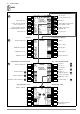
16 LED Indications, Mains Connections and Potential Differences Status Error No. Position of the Function Switch Function / Meaning LED Signals I∆N / IF ZL-N / ZL-PE / RE control) ∆U, int. ramp, EXTRA I∆N / IF MAINS/ Blinks lc2 Z L-N / ZL-PE / RE green NETZ ∆U, int. ramp I∆N / IF MAINS/ Lights up lc3 orange NETZ ZL-N / ZL-PE / RE I∆N / IF MAINS/ Blinks red lc4 ZL-N / ZL-PE / RE NETZ ∆U, int.
Status Error Position of the Function / Meaning No.
Status Error Position of the No. Function Switch Error Messages— LCD Connection Pictographs Err1 All measurements with protective conductor Err2 I∆N / IF ZL-N / ZL-PE / RE Err3 I∆N Err4 ZL-PE Err5 I∆N / IF Err6 EXTRA → PRCD Function / Meaning Potential difference ≥ UL PE (earthing contact) (frequency f ≥ 50 Hz) Remedy: inspect PE connection Note: only if appears: Measurement can nevertheless be started by pressing the ON/START key again.
Status Error No. Position of the Function Switch Err14 SETUP Err15 RLO Err16 Err17 Err18 EXTRA → ∆U RINS / RLO RE Err20 I∆N / IF Err22 Resistance compensation for the connector cables: ROFFSET > 1 Ω: OFFSET measurement of RL-PE or RN-PE and RLN for ZL-PE and ZL-N is not sensible. Remedy: check system. ROFFSET > 10 Ω: OFFSET measurement is not sensible. Remedy: check system. Z > 10 Ω: SETUP → OFFSET OFFSET measurement of RL-PE or RN-PE and RLN for ∆U(ZLN) is not sensible.
Status Error Position of the Function / Meaning No.
Status Error Position of the Function / Meaning No. Function Switch Database and Entry Operations — LCD Pictographs Err38 I∆N / IF ZL-N / ZL-PE EXTRA → tA+I∆ Err39 All (page 39) Measured Value Storage with Deviating Electrical Circuit Parameter The electrical circuit parameter selected by yourself at the test instrument does not coincide with the parameter entered under object data in the structure.
GMC-I Messtechnik GmbH 49
17 Characteristic Values Function Measured quantity Display Range Input ResoImpedance / lution Test Current 0.1 V 1V 0.1 Hz 1 Hz 0.1 V 1V 0.1 V 1V 5 MΩ UL-N 0.0 ... 99.9 V 100 ... 600 V 15.0 ... 99.9 Hz 100 ... 999 Hz 0.0 ... 99.9 V 100 ... 600 V 0.0 ... 99.9 V 100 ... 600 V UI∆N 0.0 ... 70.0 V 0.1 V 0.3 · I∆N UL-PE UN-PE f U3~ Measuring Range Connections PRO- KS-PROFiTEST Nominal Val- Measuring Un- Intrinsic Schuko INTRO ues certainty Uncertainty Adapter ±(2% rdg.+5d) 0.3 ...
Protection with two fine-wire fuse Reference Conditions Line voltage Line frequency Meas. quantity frequency Measured qty. waveform Line impedance angle Supply voltage Ambient temperature Relative humidity 230 V ± 0.1% 50 Hz ± 0.1% 45 Hz … 65 Hz Sine (deviation between effective and rectified value ≤ 0.1%) cos ϕ = 1 12 V ± 0.
17.1 Technical Data for Measurement Cables and Adapters PRO-Schuko measuring adapter (Z503K) (optional accessory) 300 V CAT III, 16 A 18 Maintenance 18.1 Firmware Revision and Calibration Information See section 4.5. 18.2 PRO-CH measuring adapter (Z503M) (optional accessory) 300 V CAT III, 16 A Note PRO-GB measuring adapter (Z503N) (optional accessory) We recommend removing the rechargeable batteries during lengthy periods of non-use (e.g. vacation).
18.3 Fuses If a fuse has blown due to overloading, a corresponding message error appears at the display panel. The instrument’s voltage measuring ranges are nevertheless still functional. Fuses– FUSE Message These fuses are active during all measurements except for voltage measurement.
19 Appendix 19.1 Tables for Determining Maximum or Minimum Display Values in Consideration of Maximum Measuring Uncertainty Table 1 Table 3 ZL-PE. (full wave) / ZL-N (Ω) Limit Max. Value Display Value 0.10 0.07 0.15 0.11 0.20 0.16 0.5 0.20 0.30 0.5 0.35 0.30 0.40 0.34 0.45 0.39 0.50 0.43 0.60 0.51 0.70 0.60 0.80 0.70 0.90 0.79 1.00 0.88 1.50 1.40 2.00 1.87 2.50 2.35 3.00 2.82 3.50 3.30 4.00 3.78 4.50 4.25 5.00 4.73 6.00 5.68 7.00 6.63 8.00 7.59 9.00 8.54 9.99 9.48 ZL-PE.
Table 5 Short-Circuit Current Minimum Display Values for determining nominal current for various fuses and breakers for systems with nominal voltage of UN = 230 V Nominal Current IN [A] Low Resistance Fuses per the DIN VDE 0636 series of standards Characteristic gL, gG, gM Breaking Current IA 5 s Limit Value [A] 2 3 4 6 8 10 13 16 20 25 32 35 40 50 63 80 100 125 160 9.2 14.1 19 27 37 47 56 65 85 110 150 173 190 260 320 440 580 750 930 Min.
19.2 At which values should/must an RCD actually be tripped? Requirements for Residual Current Devices (RCDs) Set residual current type or waveform at the test instrument: General Requirements • Tripping must occur no later than upon occurrence of rated residual current (nominal differential current I∆N). and • Maximum time to trip may not be exceeded.
19.3 Periodic Testing per DGUV Regulations 3 (formerly BGV A3) – Limit Values for Electrical Systems and Operating Equipment Limit Values per DIN VDE 0701-0702 Maximum Allowable Limit Values for Protective Conductor Resistance for Connector Cables with Lengths of up to 5 m Test Standard Test Current RSL Housing – Mains Plug Open-Circuit Voltage 0.3 Ω 1 VDE 0701-0702:2008 1 2 > 200 mA 4 V < UL < 24 V + 0.1 Ω 2 for each additional 7.
19.
19.6 Keyword Index A Abbreviations .......................................................................... 58 Adjusting Brightness and Contrast .......................................... 11 ÖVE-EN 1 ......................................................................... 6 VDE 0413 ....................................................................... 25 Symbols ................................................................................... 7 B T Batteries Charge Level ......................
19.7 Bibliography Statutory Source Documents Further Literature in German German occupational safety legislation (BetrSichV) Regulations issued by the accident insurance carriers Title Author Publisher Bödeker, W. Lochthofen, M. 2015 Prüfung ortsfester und ortsveränderlicher Geräte HUSS-MEDIEN GmbH 8th edition, Berlin 2014 www.elektropraktiker.de ISBN 978-3341-01614-5 2014 Wiederholungsprüfungen nach DIN VDE 105 Bödeker, K.; Lochthofen, M.; Roholf, K. Hüthig & Pflaum Verlag 3rd edition, www.
20 Repair and Replacement Parts Service Calibration Center* and Rental Instrument Service If required please contact: GMC-I Service GmbH Service Center Beuthener Straße 41 D-90471 Nürnberg, Germany Phone: +49-911-817718-0 Fax: +49-911-817718-253 e-mail: service@gossenmetrawatt.com www.gmci-service.com This address is only valid in Germany. Please contact our representatives or subsidiaries for service in other countries. * DAkkS calibration laboratory for electrical quantities, registration no.
Prepared in Germany • Subject to change without notice • PDF version available on the Internet GMC-I Messtechnik GmbH Südwestpark 15 D-90449 Nürnberg, Germany Phone: +49-911-8602-111 Fax: +49 911 8602-777 e-mail info@gossenmetrawatt.com www.gossenmetrawatt.